Switch Box X Build Log

This was a pretty fun (and tricky!) project, so I wanted to recap how it came together, what I messed up, what I did well, the whole shmageggy (any by that I mean: in way too much depth). Let’s jump into it!
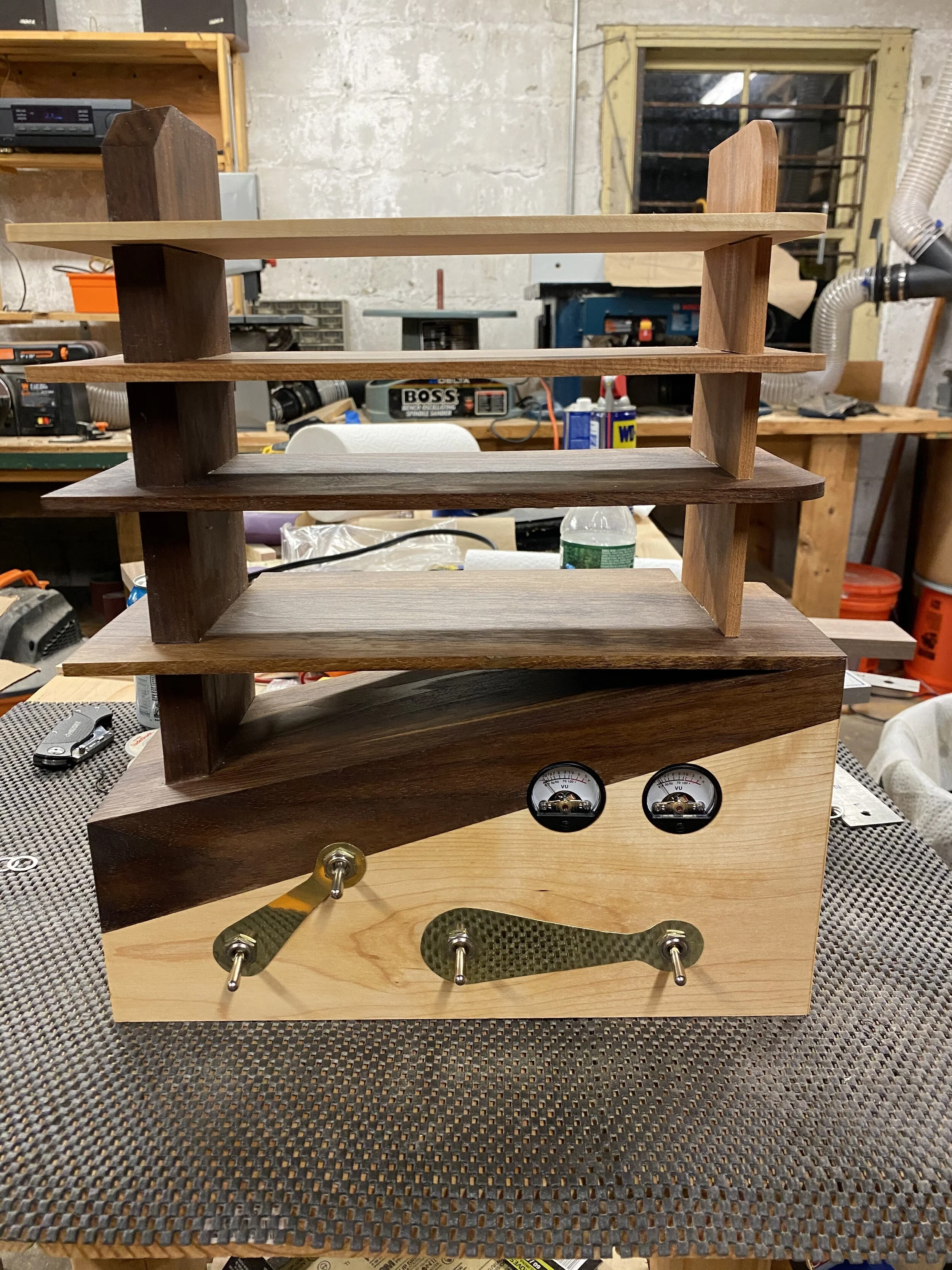
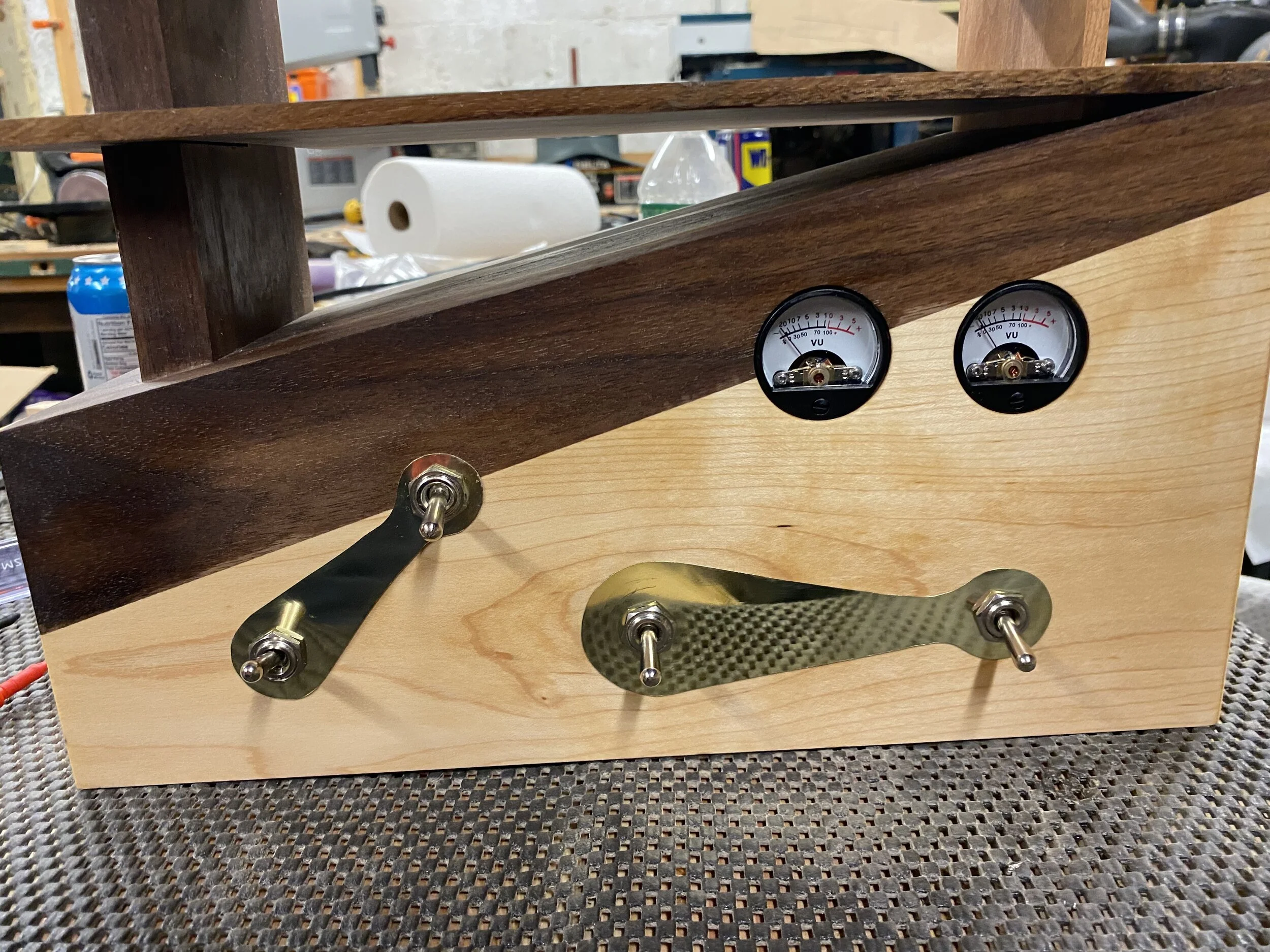
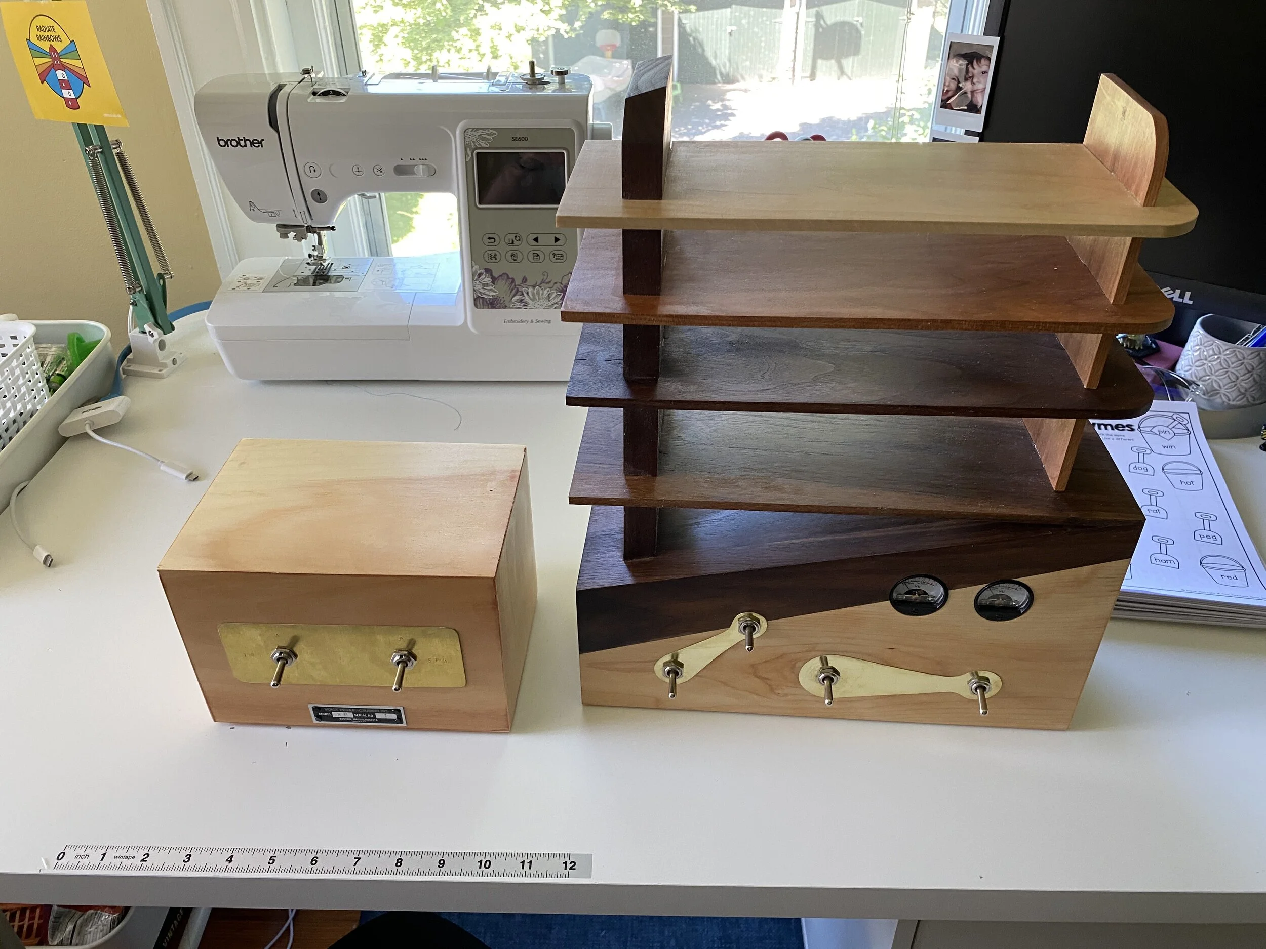
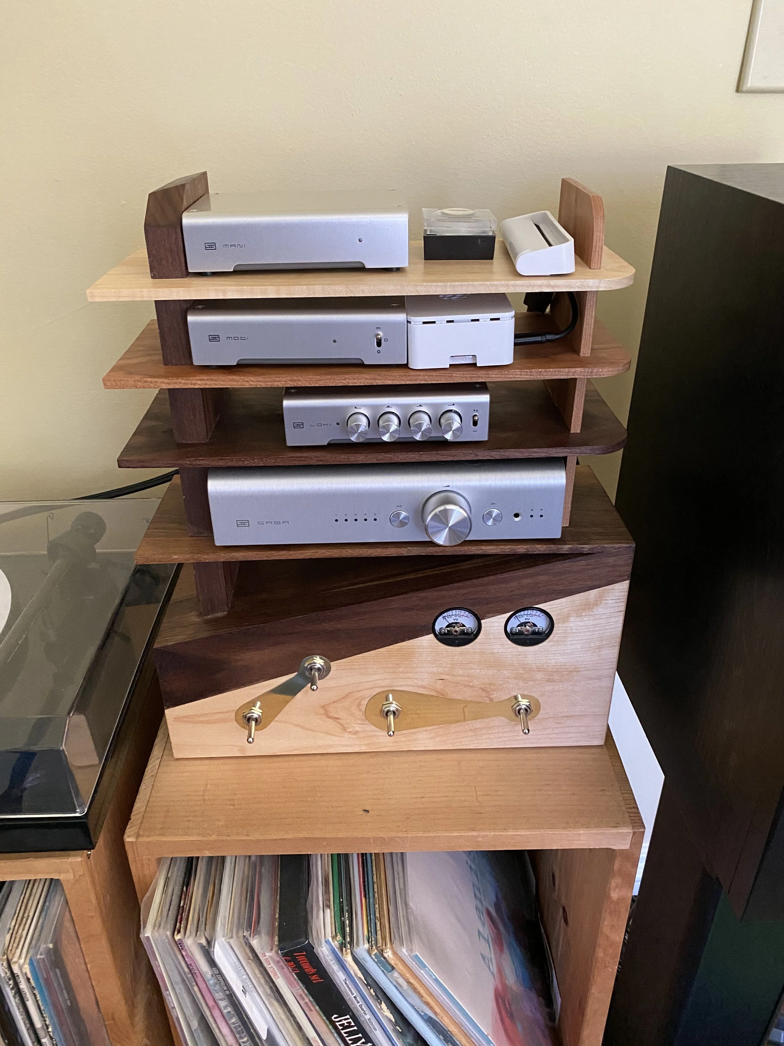
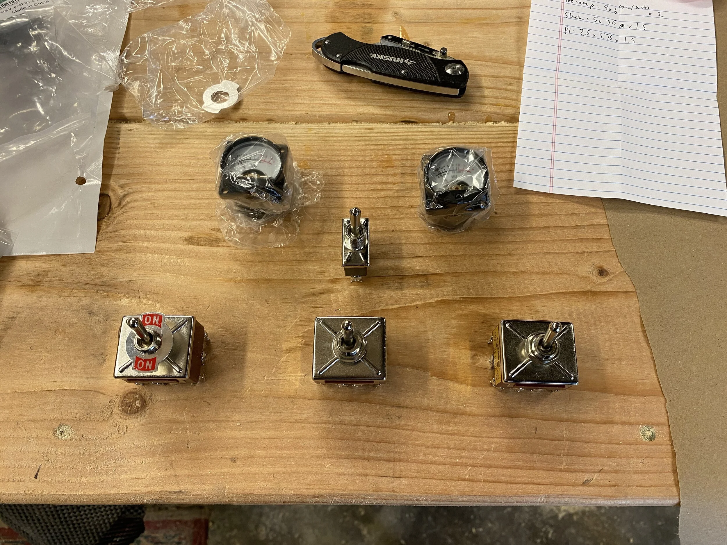
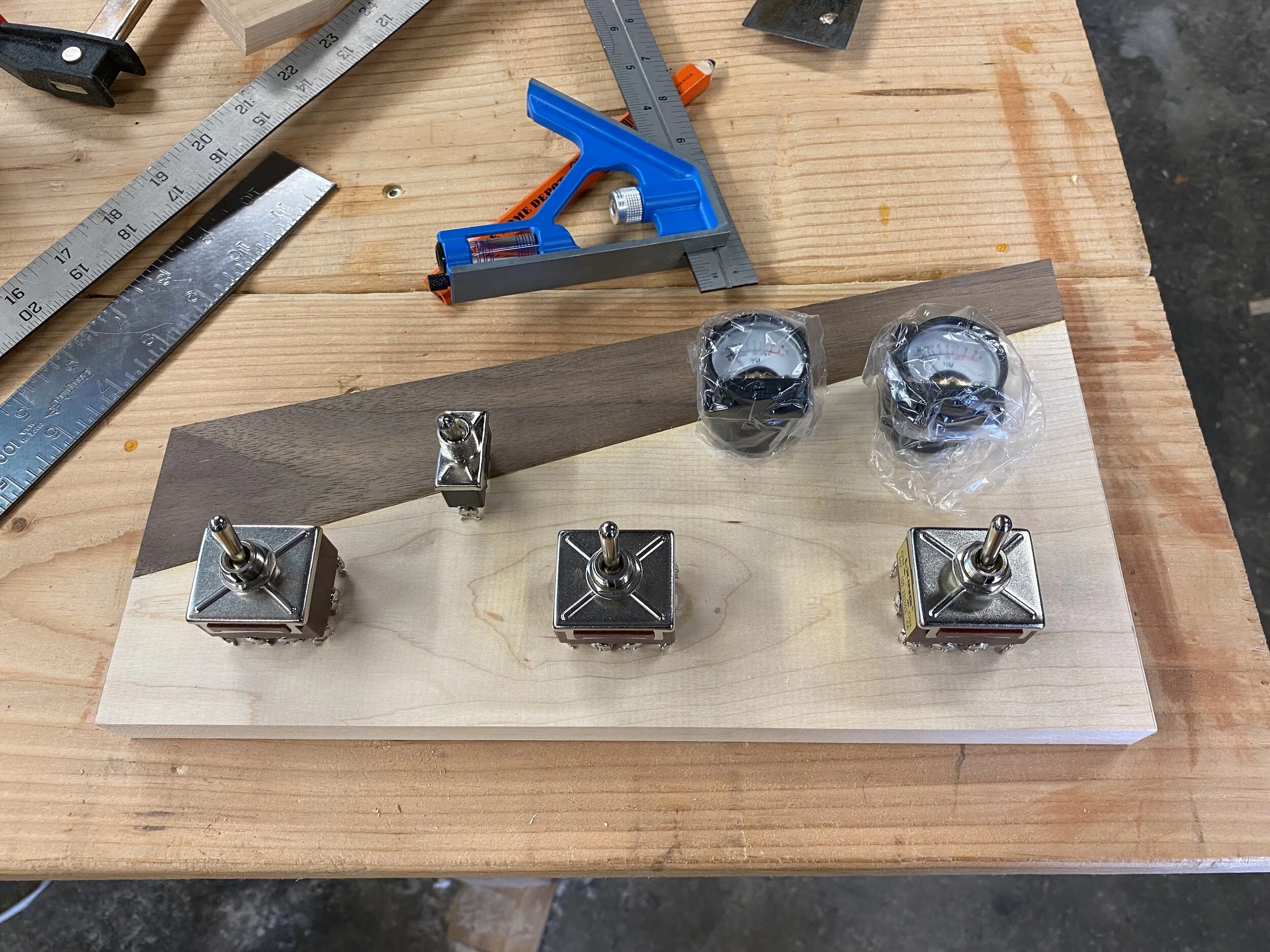
First, what exactly is this thing and what does it do? The basic idea is that I have 2 amplifiers, a tube amp and a solid state amp, and one set of speakers, and I need a way to switch which amp is currently driving the speakers. That’s the right-most switch: it controls which amp is currently connected to the speakers. I also need to switch which amp the input signal is going to. That’s the middle switch. These two switches should always be in the same position as each other (I considered using a relay so that there was only one switch, but I am not an electronics wizard and didn’t feel like doing that deep dive given the other stuff I had planned). I also have 2 inputs into this system: a turntable and an internet streamer. That’s the left most switch. The top switch is a power switch for the little VU meters. Above the switch part, you can see all the stacked stereo components. From the bottom up in the picture above, we’ve got a Schiit Saga S pre-amp, Loki tone control, Modi DAC, Raspberry Pi 4 running Volumio, and finally a Mani Phono Preamp (these are all at https://www.schiit.com/). The amplifiers in question are a Reisong A10 Tube Amp (you can get that either from Amazon, or China Hi-fi, the shipping is a big chunk of the price and highly variable), and a Schiit Aegir power amp.
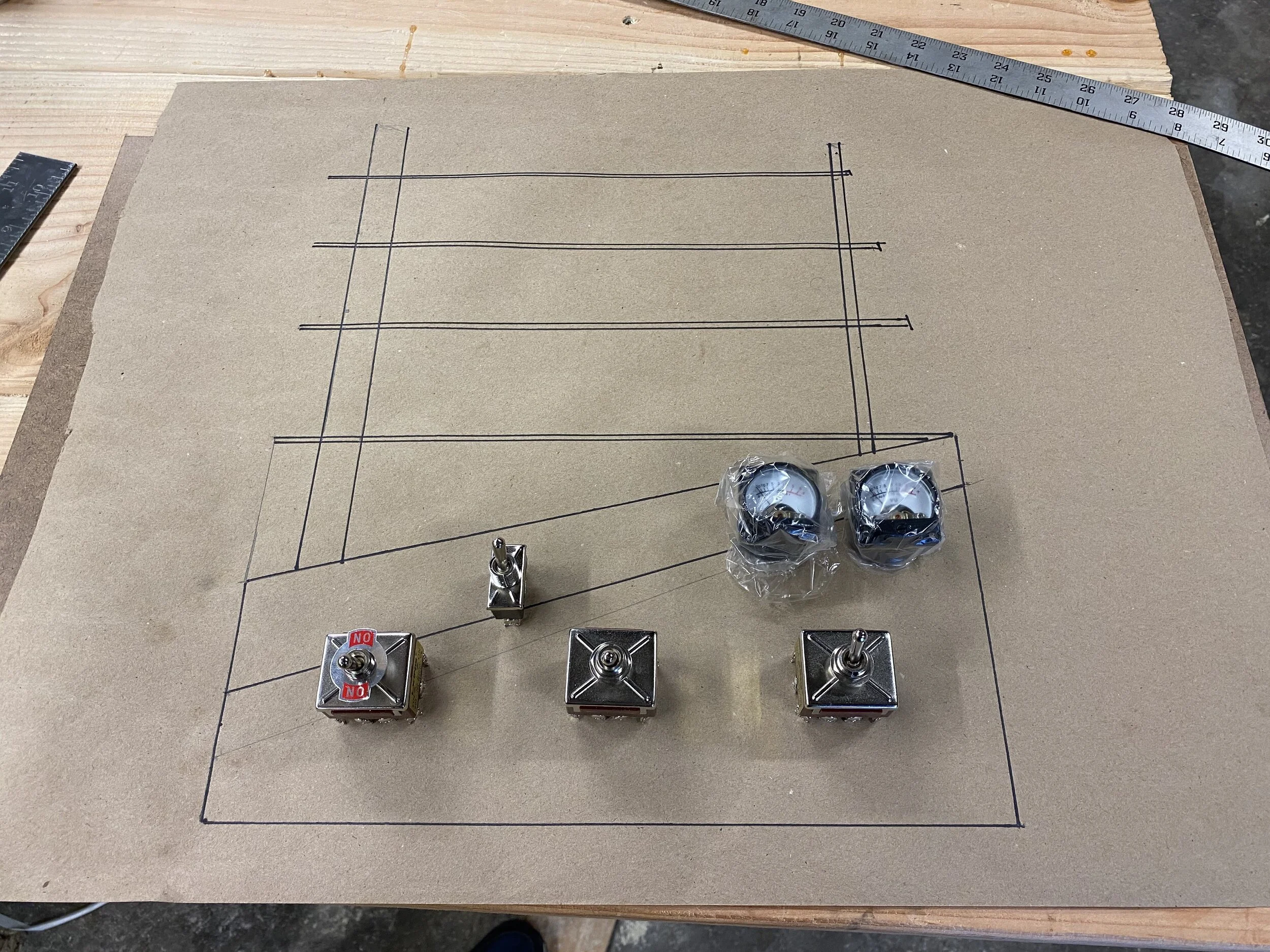
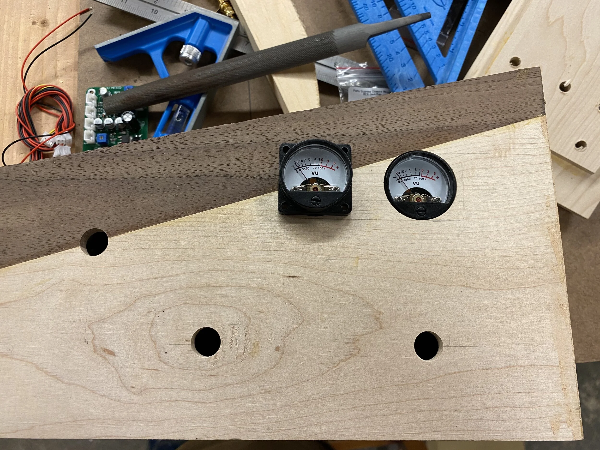
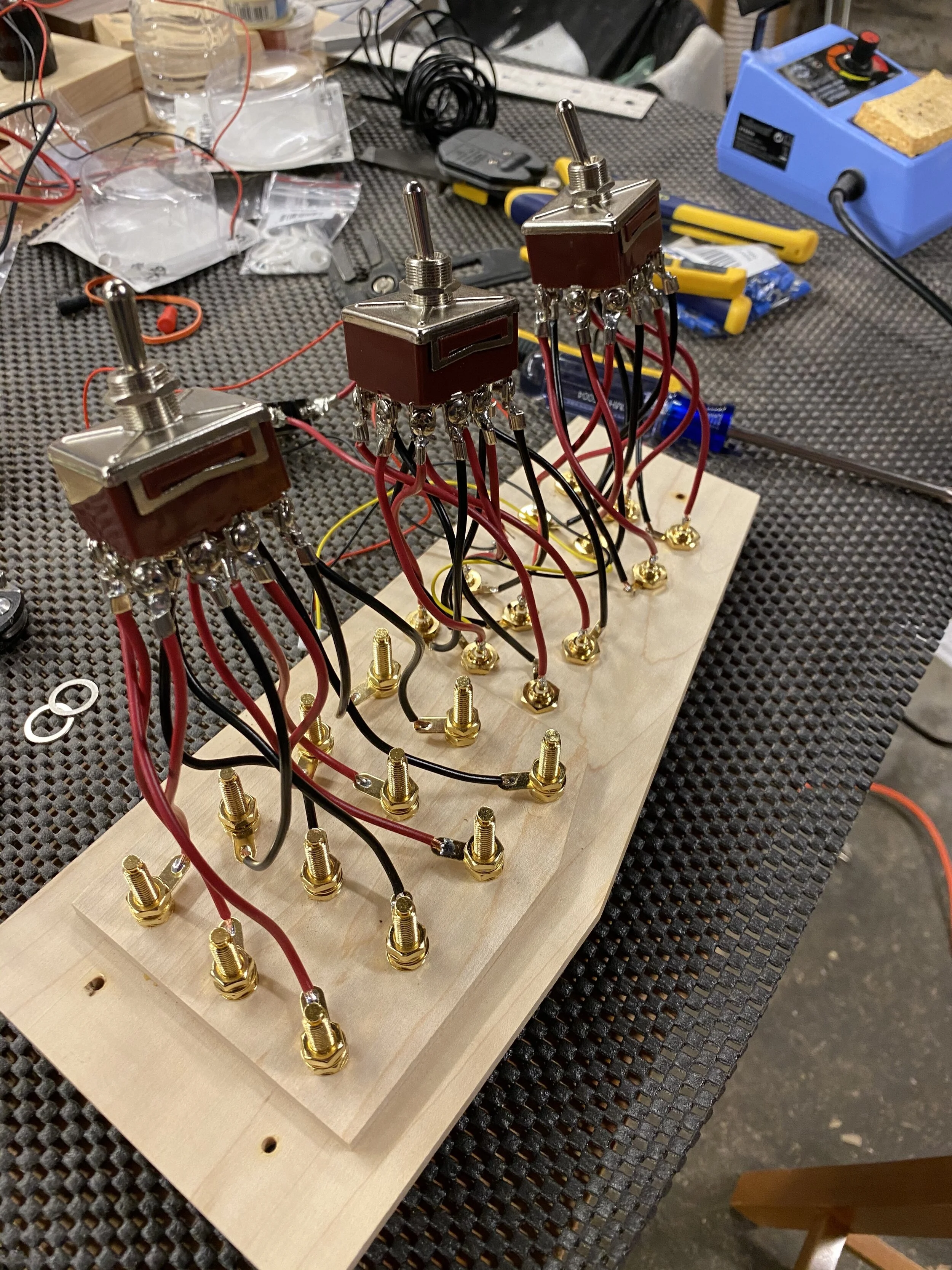
For the design, I wanted something sort of mid-century modern-ish. The vibe should I was going for was sort of a vintage radio/radio tower look. Initially I was just going to have switches, but then I found a VU meter kit on Amazon, and thought that it would be cool to incorporate that too. Below on the left you can see the components: 3 4PDT switches (that means “4 pole double throw”, which basically means is switches 4 wires at a time. The back of it has 3 rows of 4 connectors, and the switch controls whether the top row or bottom row is electrically connected to the middle row). We also have a simple power toggle, and of course, the VU meters. On the right, you can see the final drawing I came up with, at 1:1 scale. I put the components on it to get a basic idea of how it would all fit, making sure I accounted for the edge width of the wood.
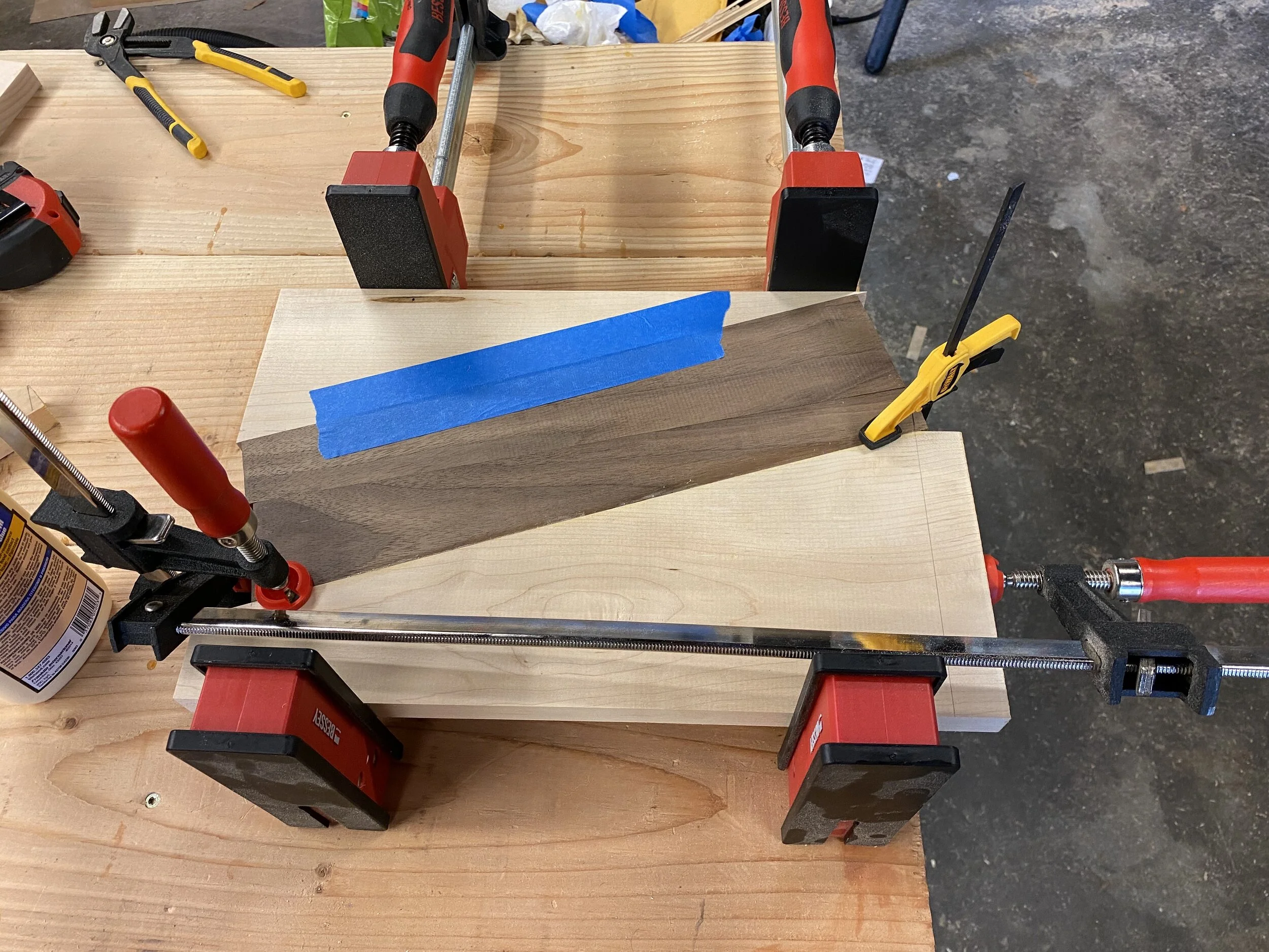
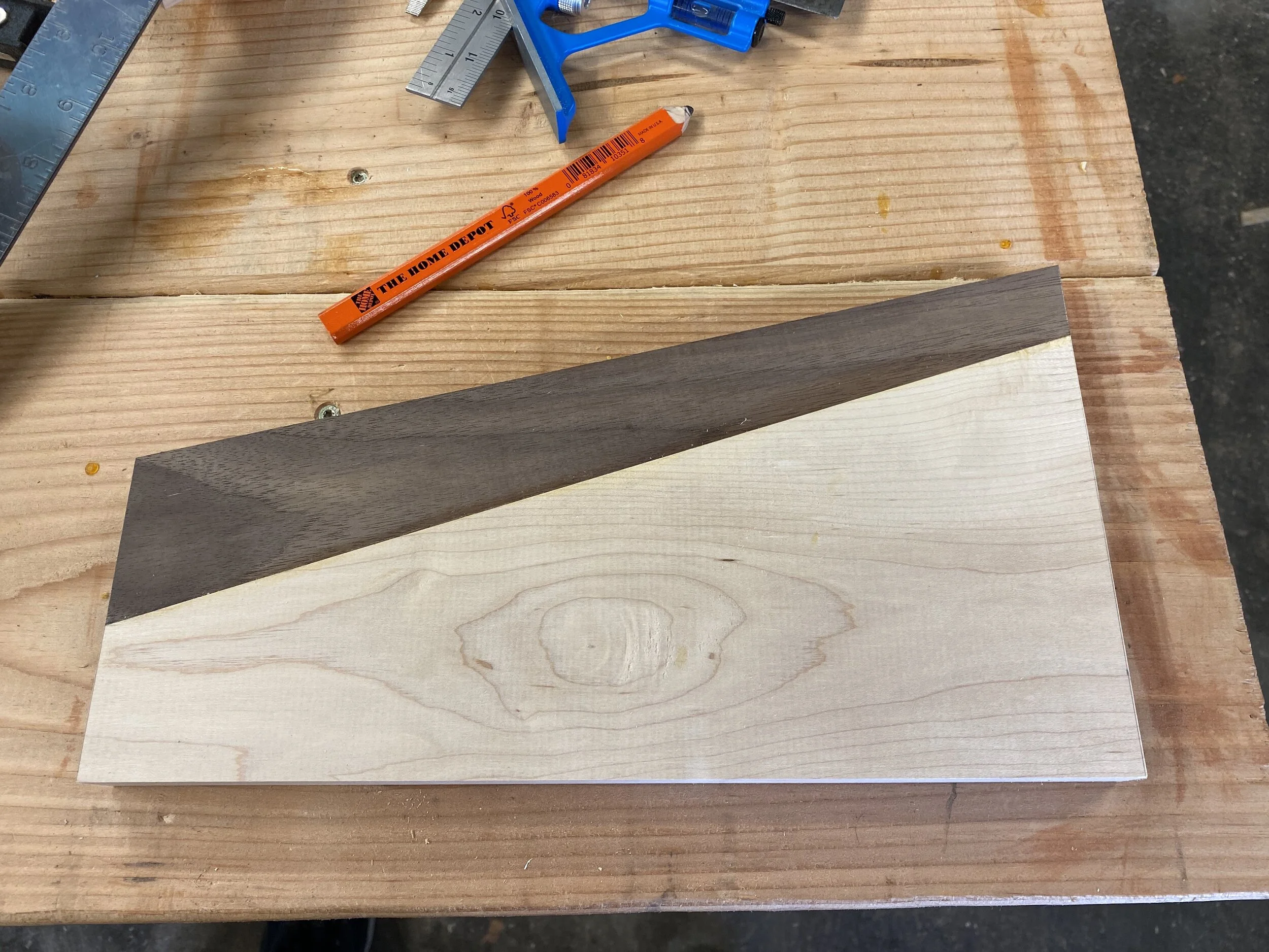
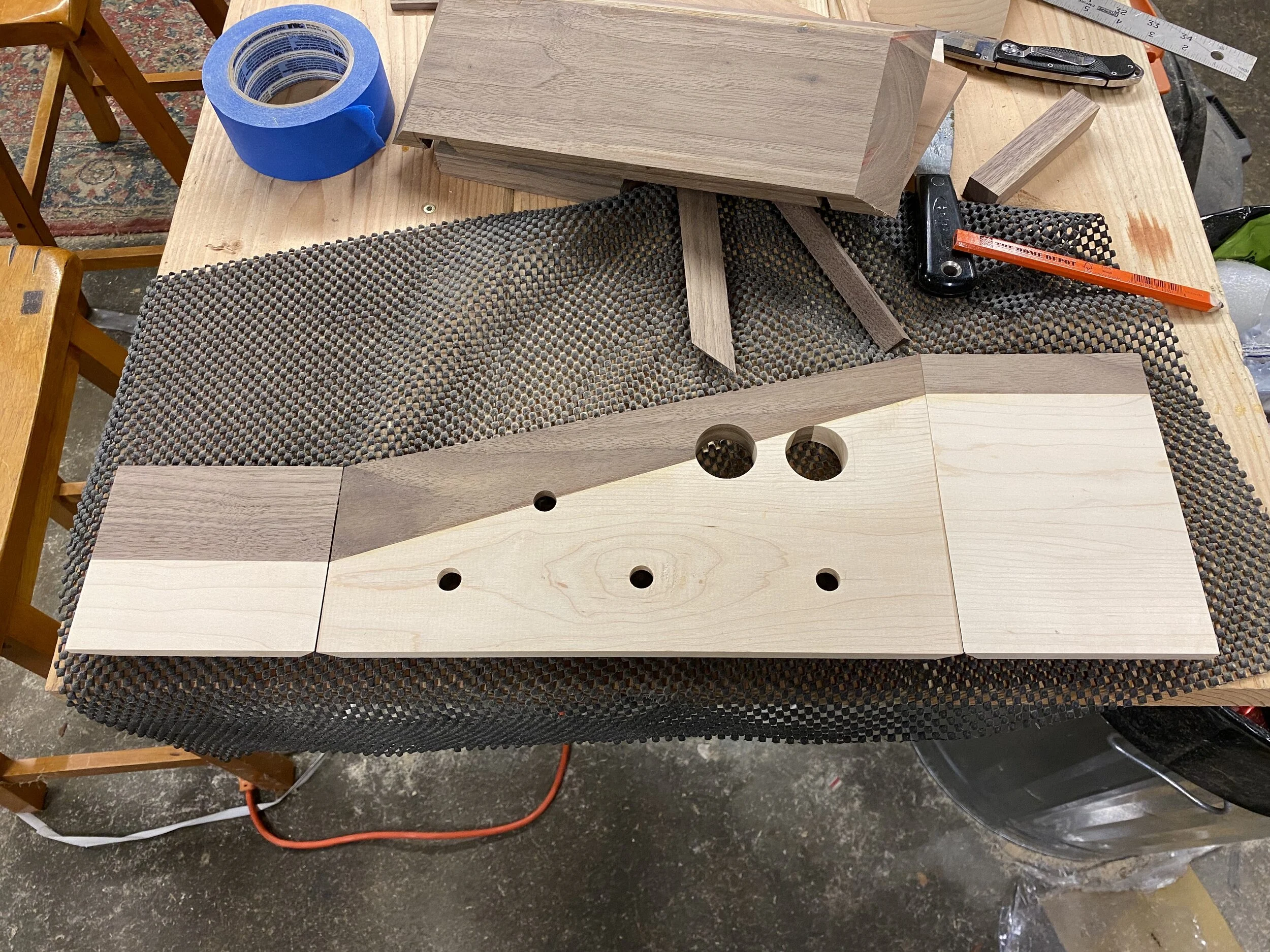
First order of business was making the front panel. Cutting this was tricky, because I’m basically doing an angled rip cut. I don’t have pictures of the jig I made, but I screwed a sacrificial piece of pine at the angle I wanted into a bit of plywood, cut that, and then I had a wedge of pine that I could use to cut the maple/walnut pieces at the angle I wanted. Because I had just cut a rectangular board into 2 “mated” trapezoids, I could reassemble them to create a big rectangle, which is what I did below on the left in order to glue it up. The top piece of maple and walnut are held together with painter’s tape, then there’s the 2 pieces of walnut and maple I was actually gluing together. Once they were glued, I could square up the sides. On the right, you can see the final glued up and squared off front piece.
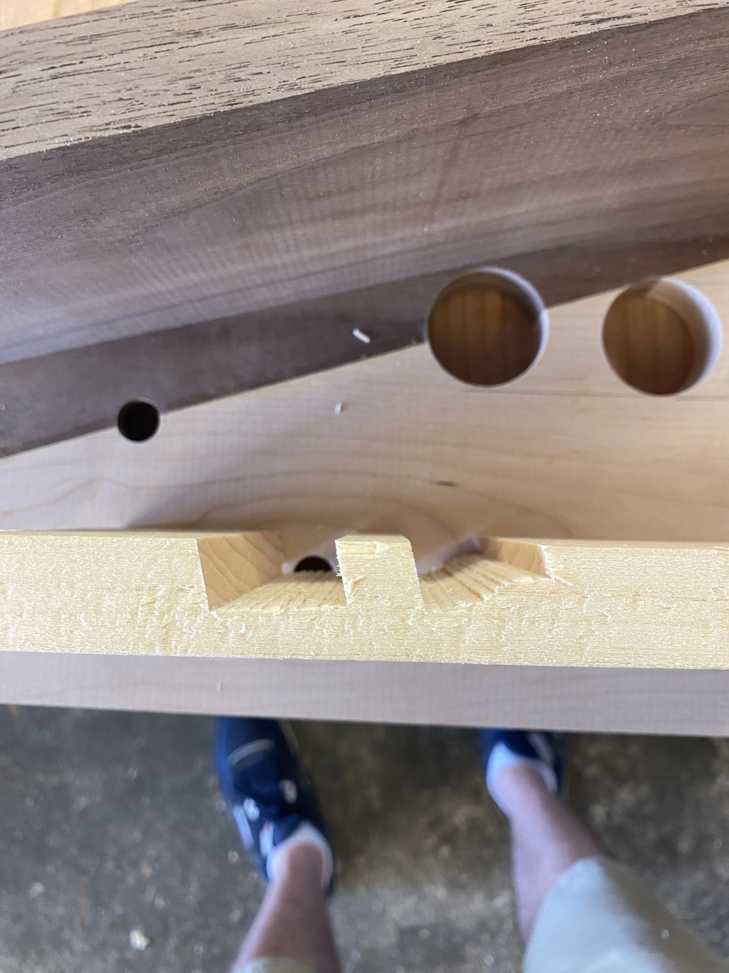
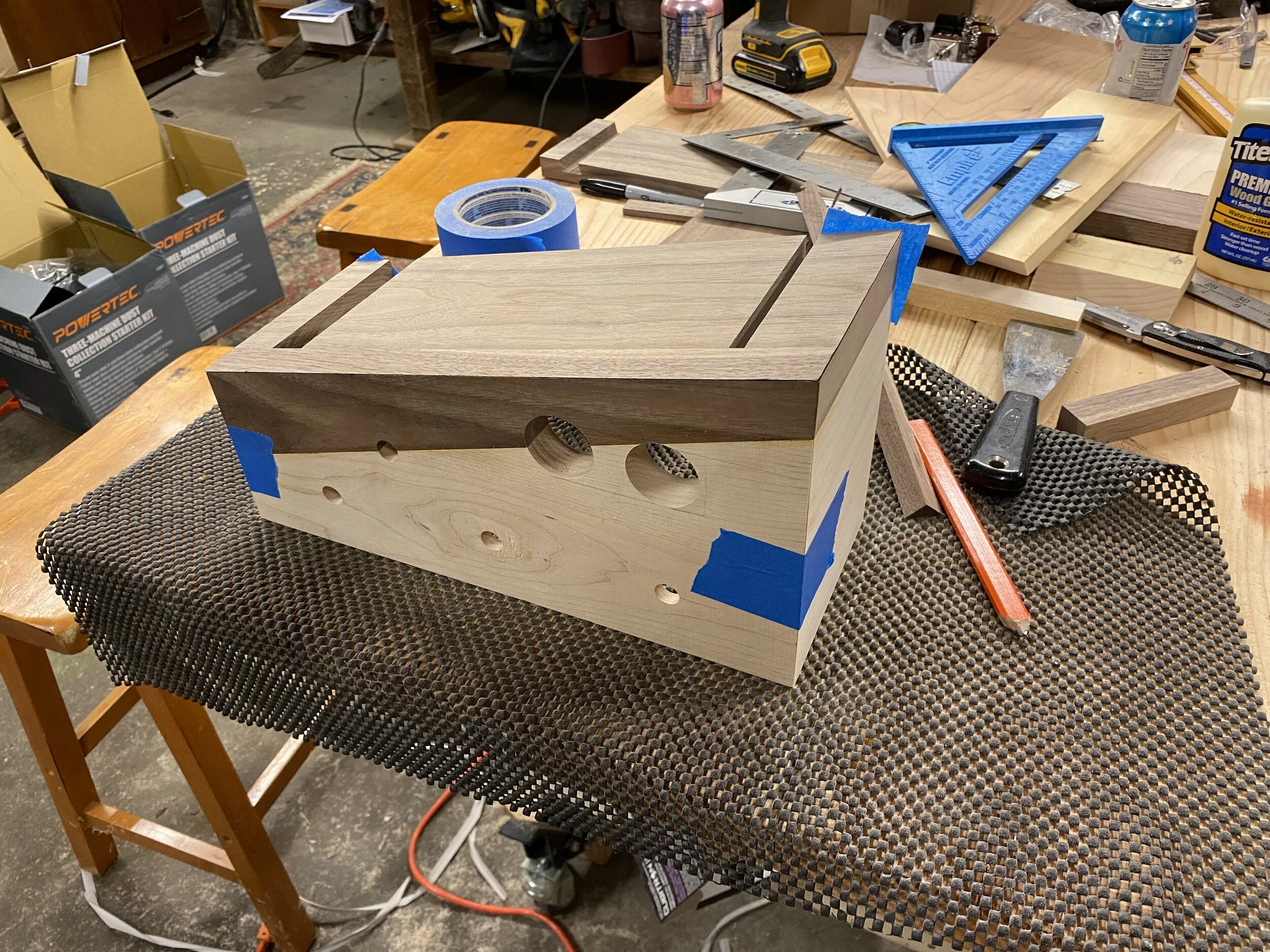
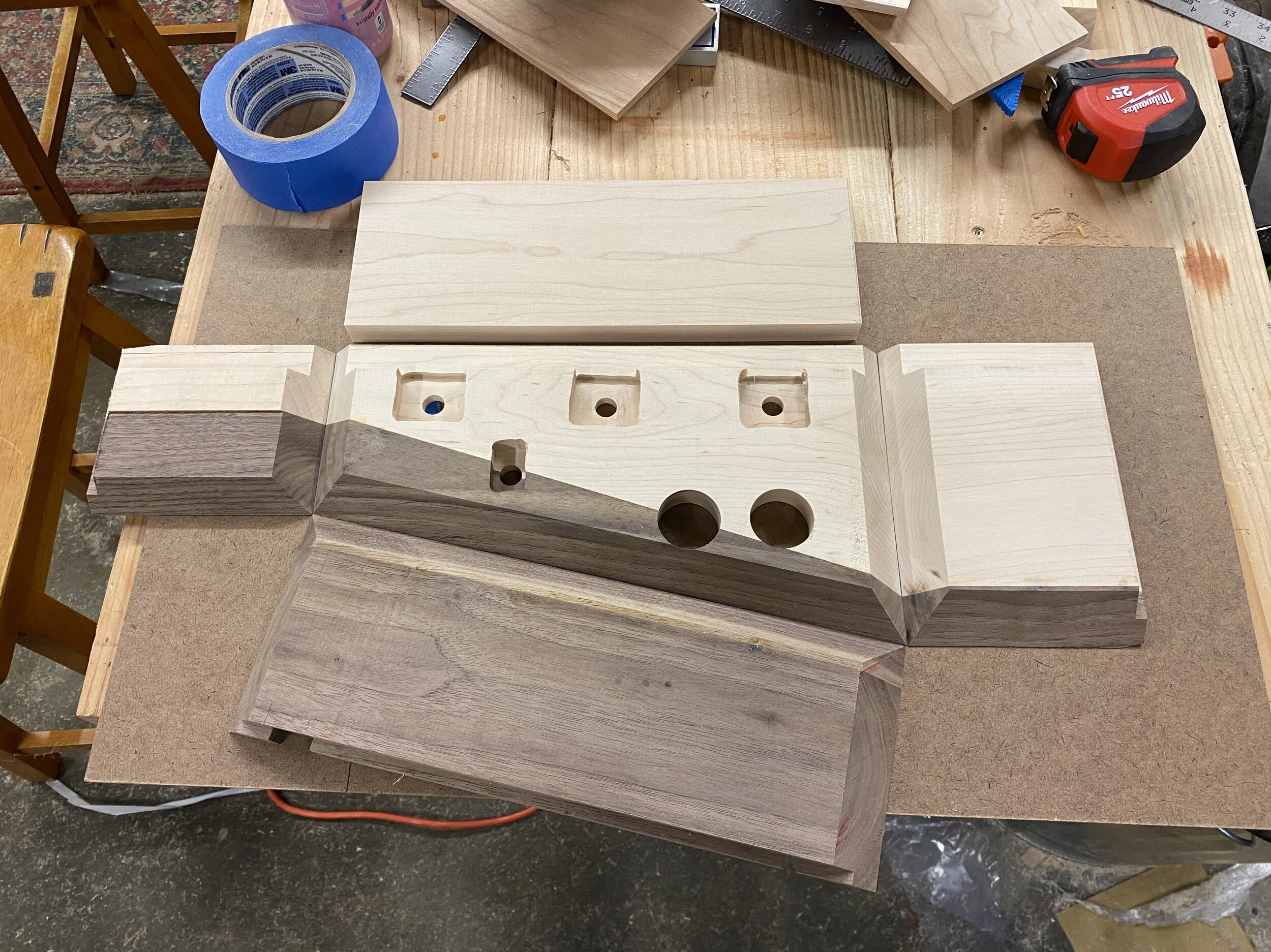
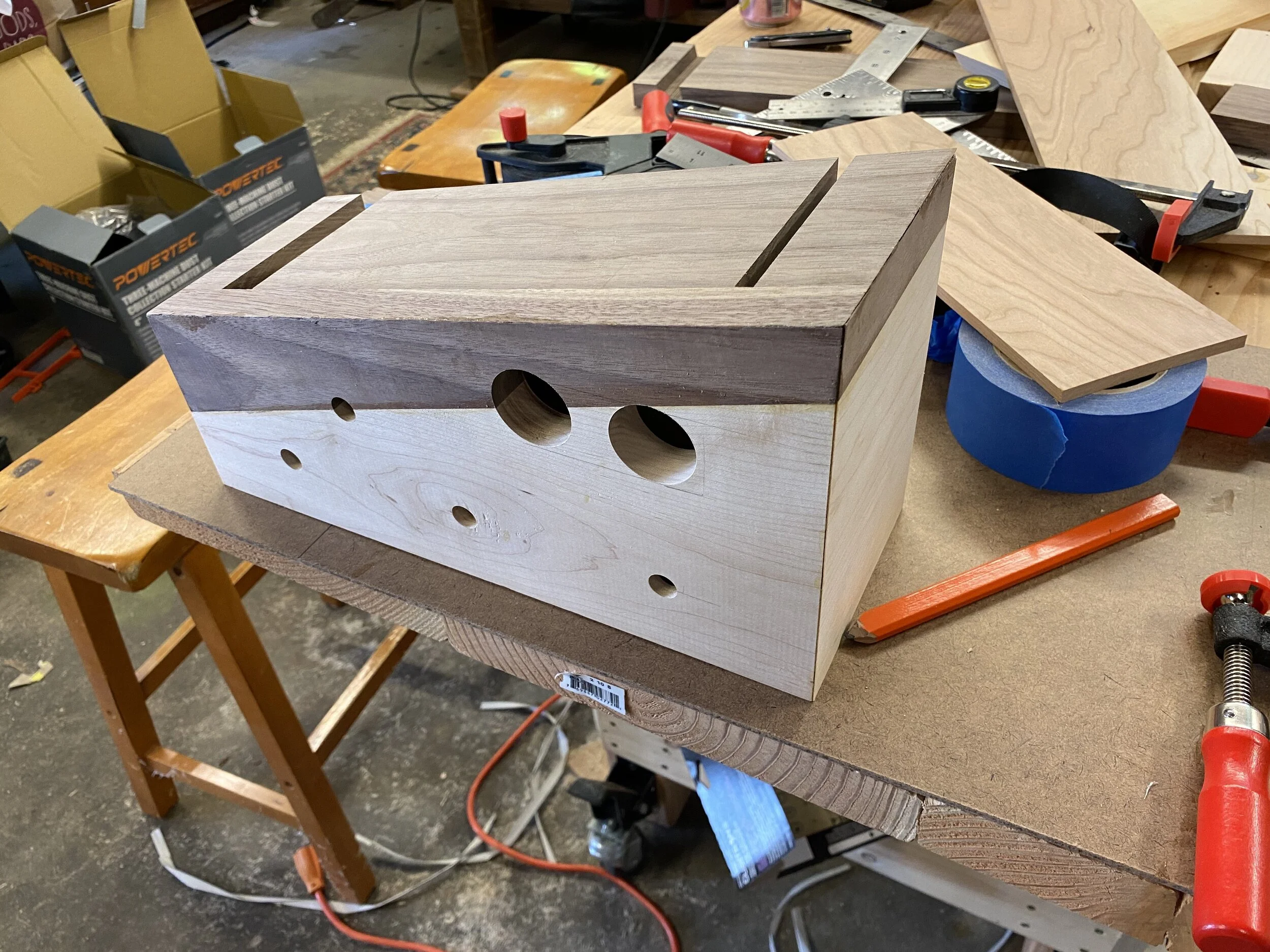
Next, I needed to lay out where the holes for the switches and meters would go. The switches were equidistantly spaced along the bottom, one VU meter was aligned with the center of the switch, and the other VU meter I wanted bisected by the walnut. Same for the power switch: centered between 2 switches, cut in half by the walnut. I drilled these out with forstner bits, and then used a router to carve out enough space for the switches to sit in on the back side. As you can see, my freehand routering is less than precise, but this matters 0%, it’s totally hidden.

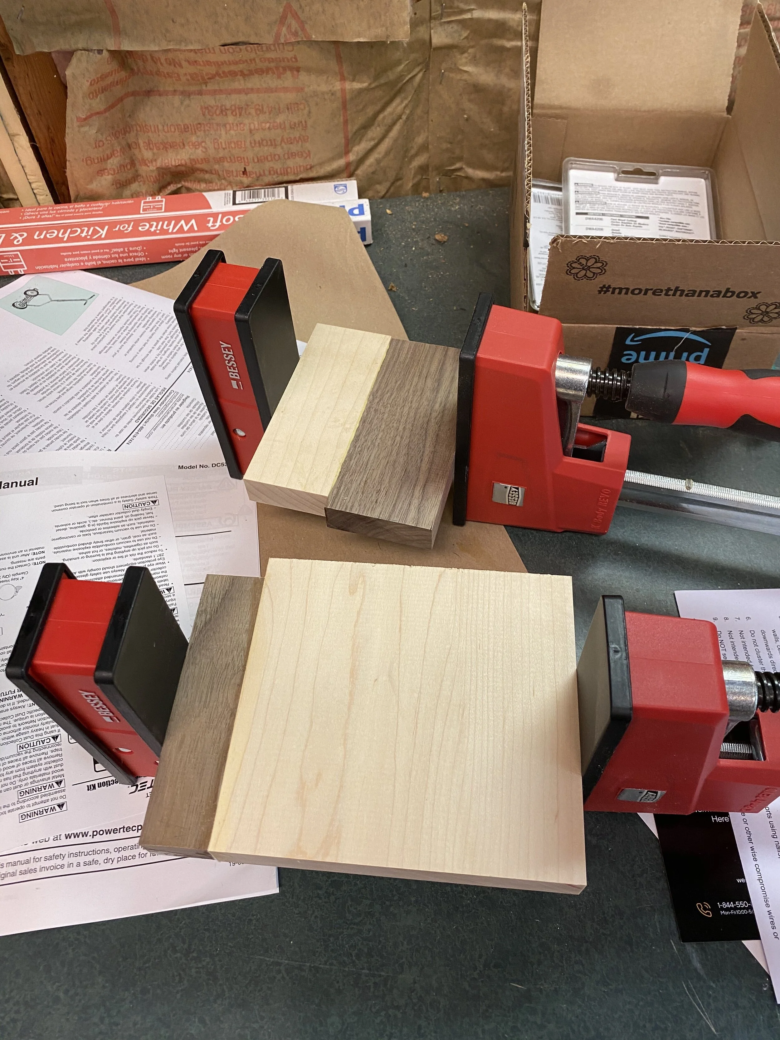
Here are the sides being glued up. I made each section slightly larger than it needed to be so I could afford to make some mistakes later. Also you can see some of the random detritus around the shop, including used fluorescent lights and the owner’s manual for a reel mower. They are not part of this project. I do love the Bessey parallel clamps, although I bought 50” ones on the internet without appreciating how big 50” really is, they’re slightly overkill at times. I got some 24” ones for when I don’t need to be gluing entire bowling lanes together.
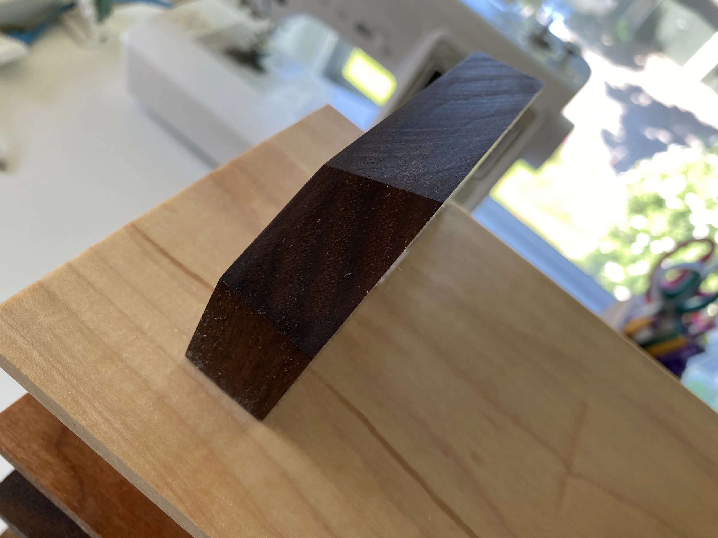
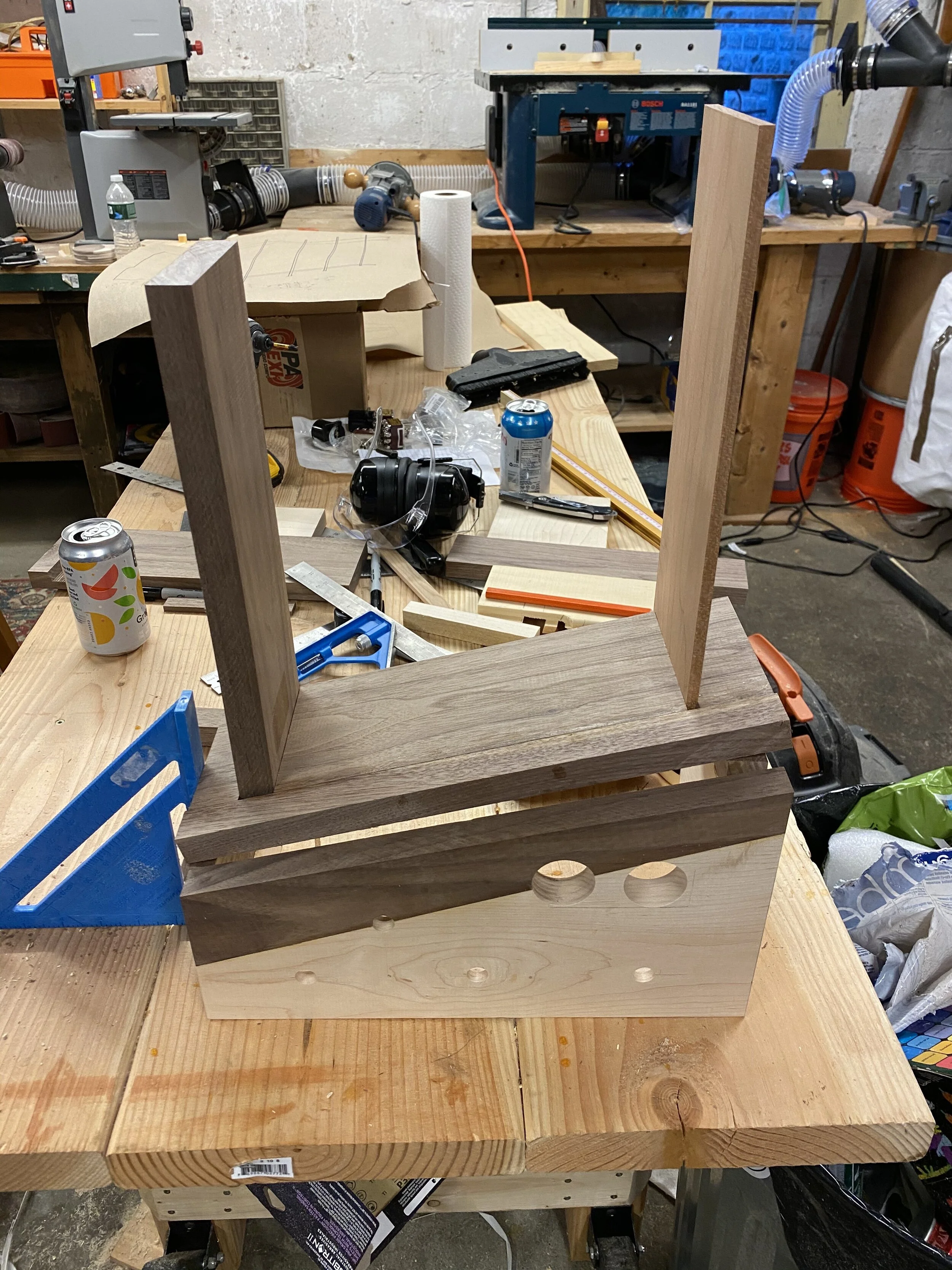
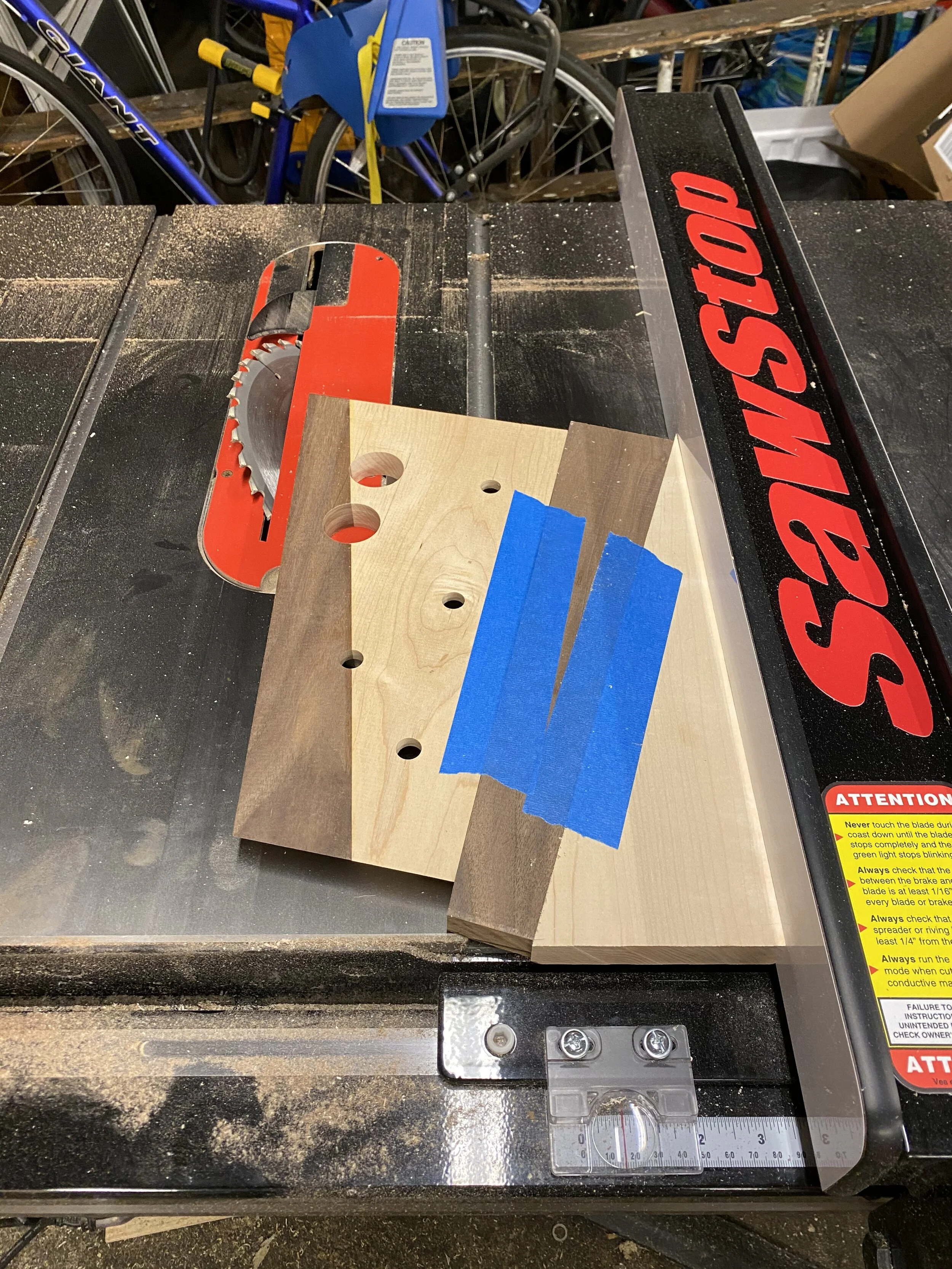
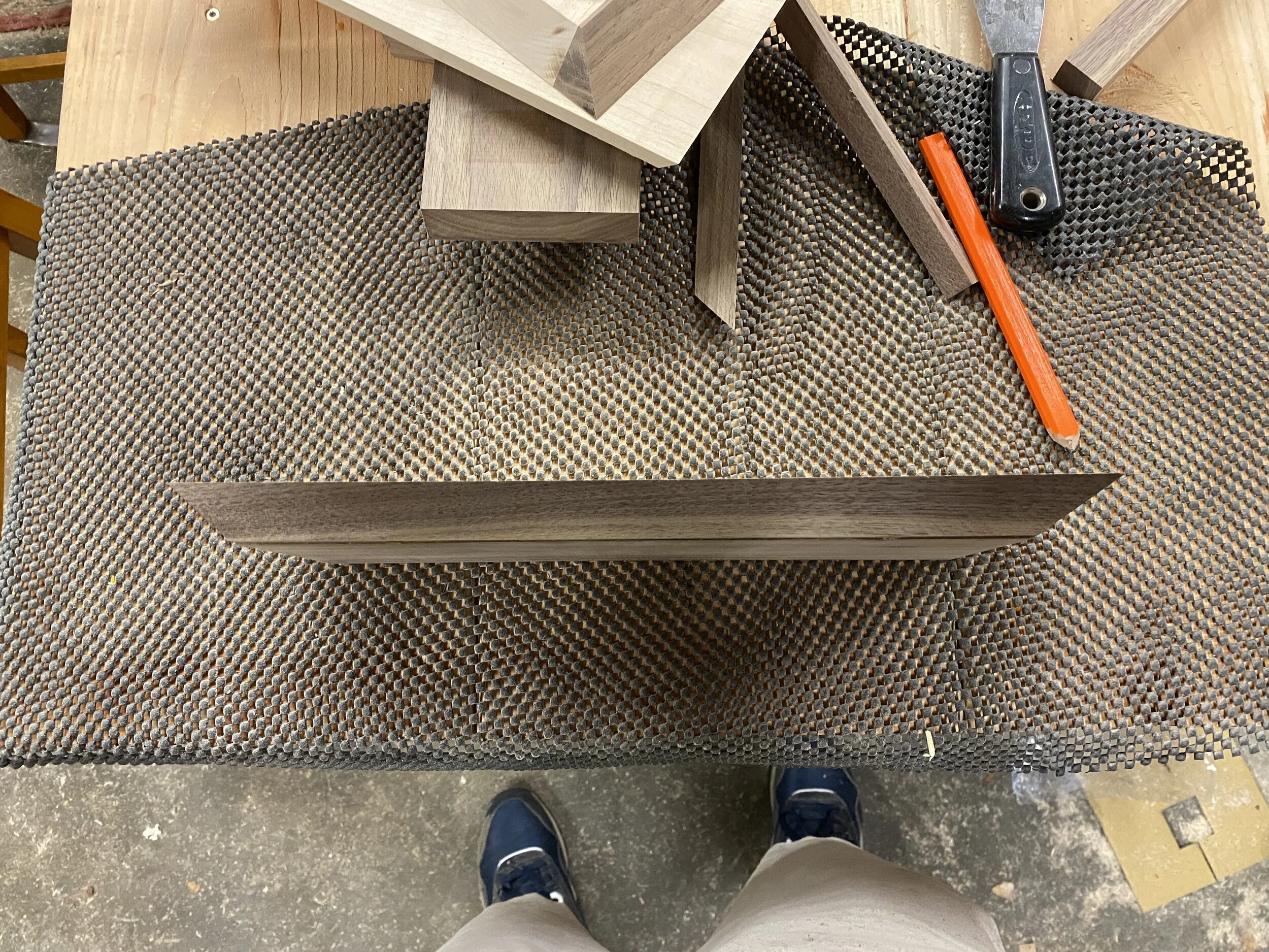
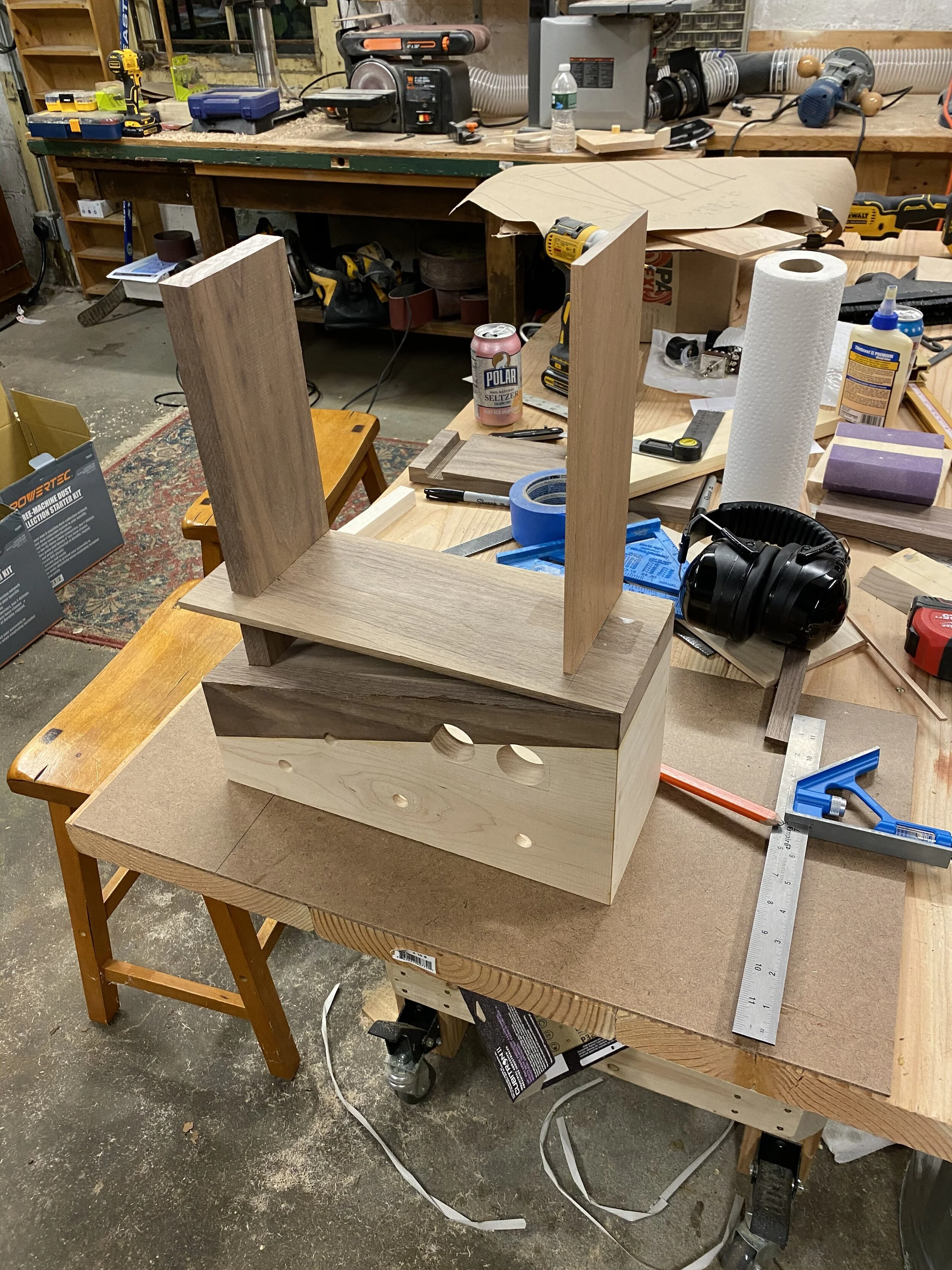
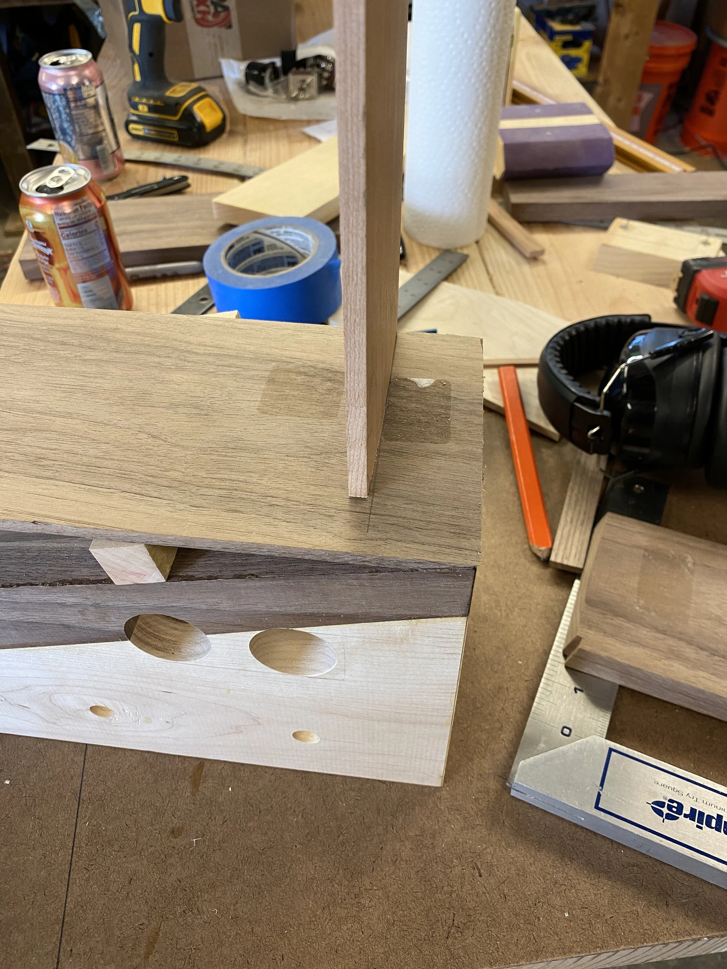
Now we get into the main supports for the shelves. I had to cut the grooves at an angle, so in the first picture, you can see two test runs: First I tried varying the depth of the table saw blade (the cut on the right), which would support a squared off bottom on the support. Then I realized I could just cut the support’s bottom at an angle, and make the same depth cuts with the table saw. I wasn’t using a dado blade here, just my regular blade, which is why the bottom is a bit jagged. No one would see it, flood it with glue, good to go. You can see in the 2nd picture how the cut looks in the walnut, and how the bottom of the support is slightly angled. I wanted the supports set back from the front edge, because I wanted a nice clean mitered look there, but there was no good way to cut the groove for the support only partway through a piece of walnut, so I just the groove all the way through, then glued a strip onto the front, which you can see in the 3rd picture. The 4th picture is the walnut and thinner cherry supports as they’d stand, with everything just balanced precariously. Originally, the cherry support was much taller than the walnut one, I thought it would look neat to have the whole piece kind of slope up and to the right, but once I started dry fitting everything together, I wasn’t a fan of that look.

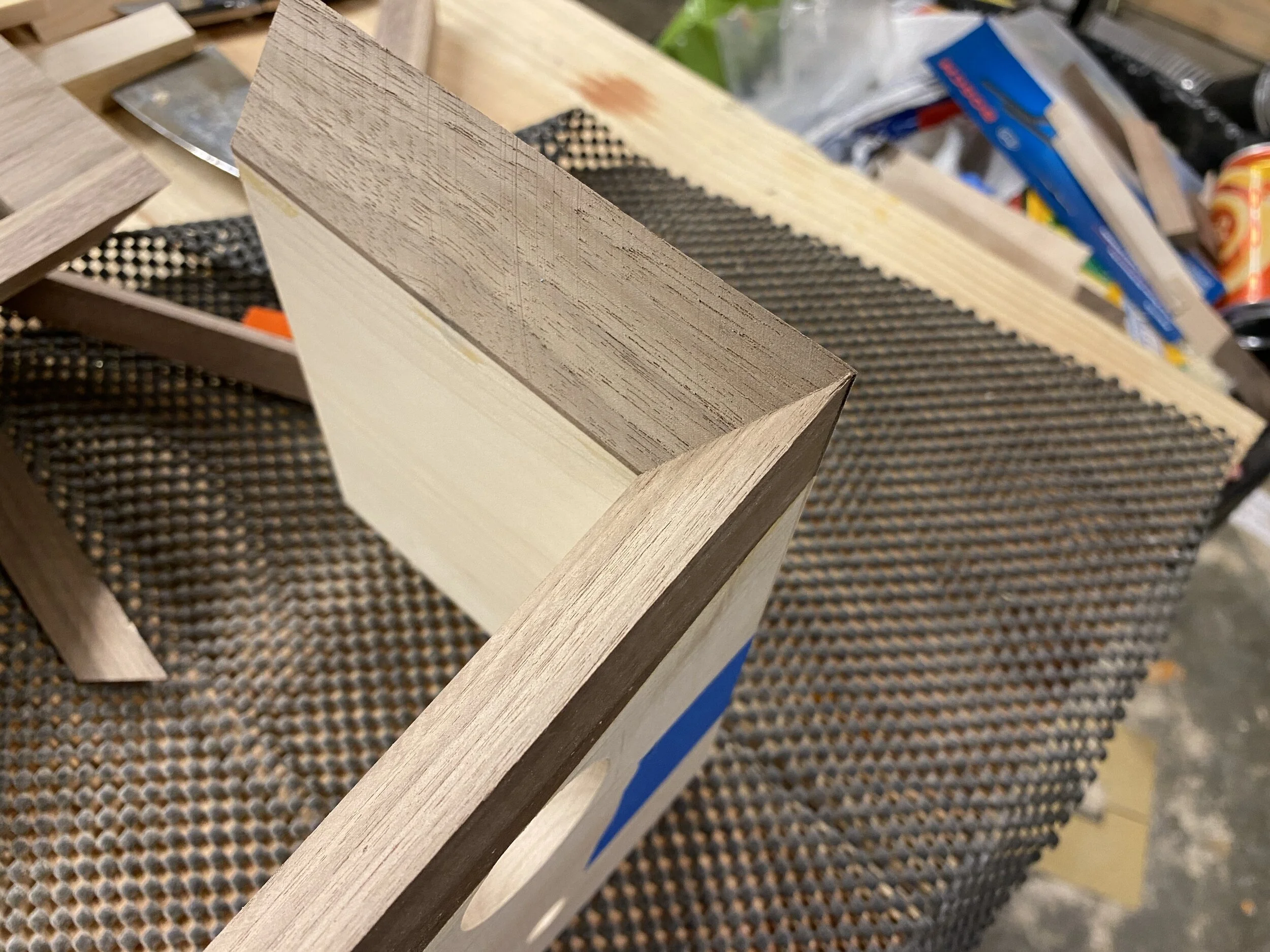
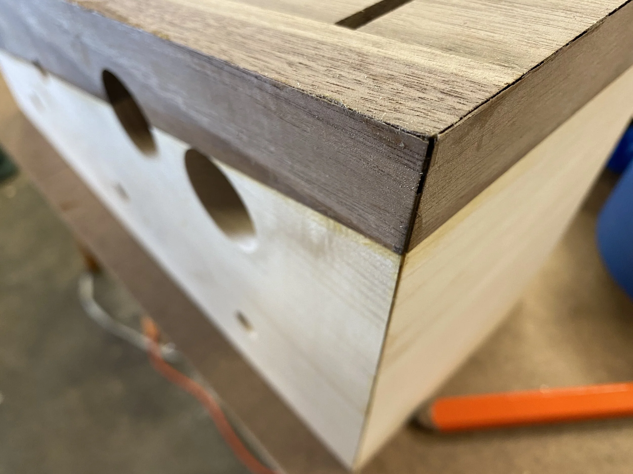
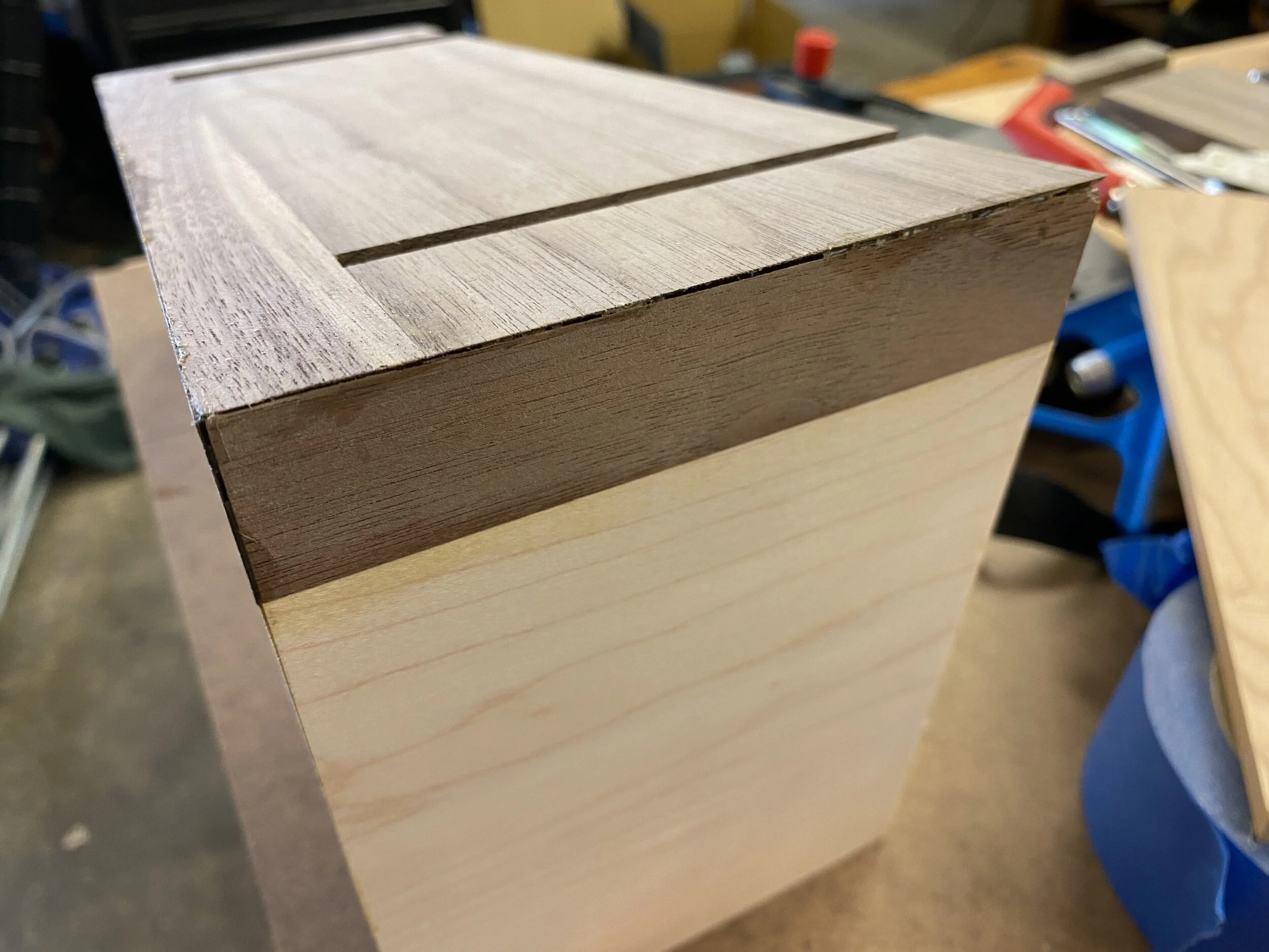
Time for some miters! These long edges needed to be cut on the table saw, and I used the leftovers from the initial cuts (showed above in the glue up stage) to get the top edge of the box square to the blade. Fancy move! The 2nd picture shows the miters on the top piece: 45 degrees on the front, and then something like 58 on the left and 77 degrees on the right for those miters on the left and right side of the top, since the whole top sits at an angle. The next two pictures a closeup of one of those top corner miters, and then a dry fitup to make sure I was at least close before breaking out the glue. This was the first time I got a real sense of what the box would look like, and I was pretty pleased!
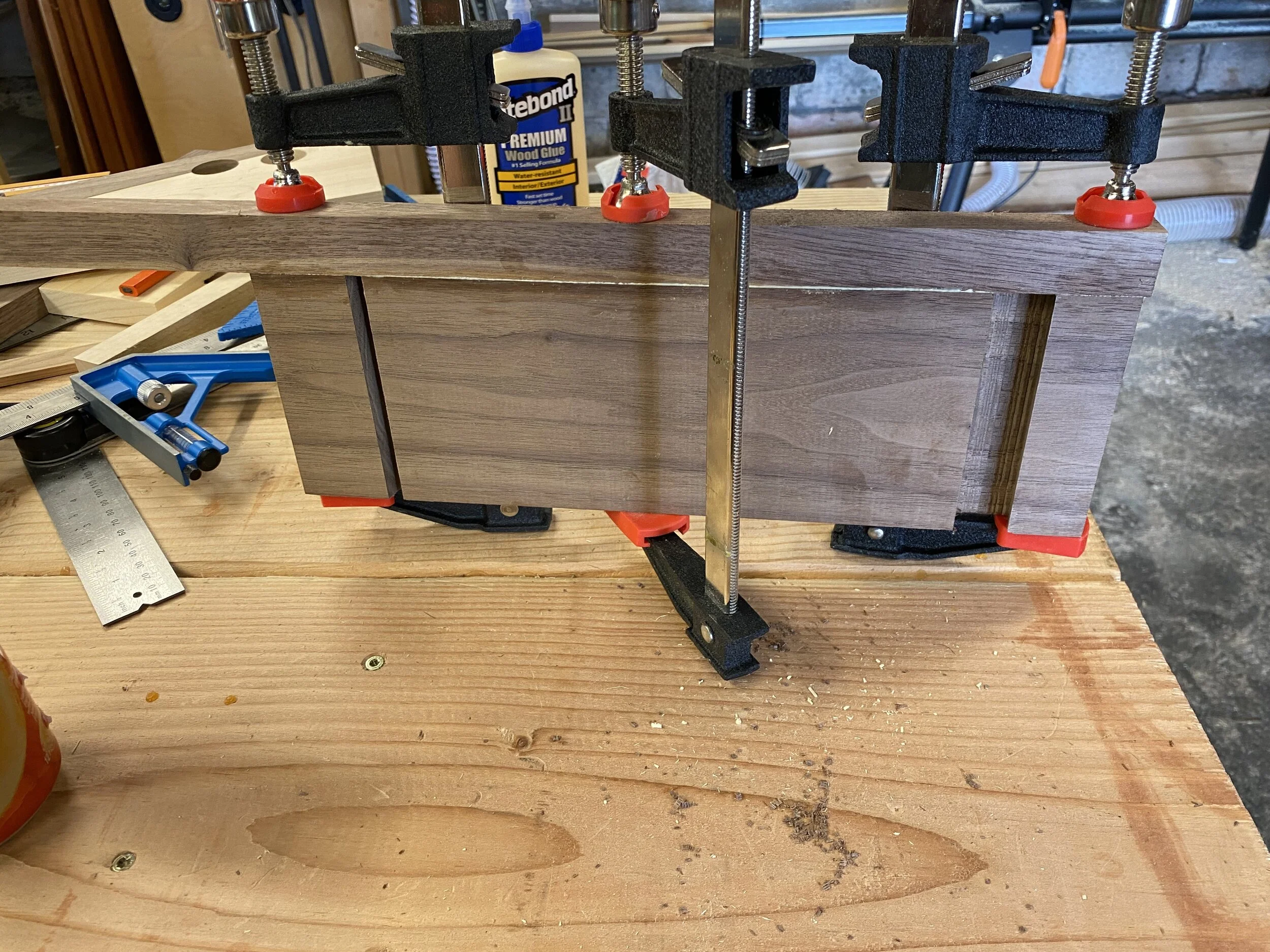
Next, it was time to glue the box together for real. The bottom of the box isn’t mitered, you can see the rabbets it sits in. There’s no real reason to have the bottom mitered, and each mitered edge adds additional complexity because they’re super tricky to clamp. The first two pictures show the “exploded” view, and then you can see the combination of tape and clamps to hold everything together. Finally, there’s the finished glued up box. The front edge and left side miters came out fantastic, the right edges are good but not perfect. Ah well.

Gaze upon my failures. Wood putty, and the addition of the first shelf, wound up mitigating both of these pretty well.
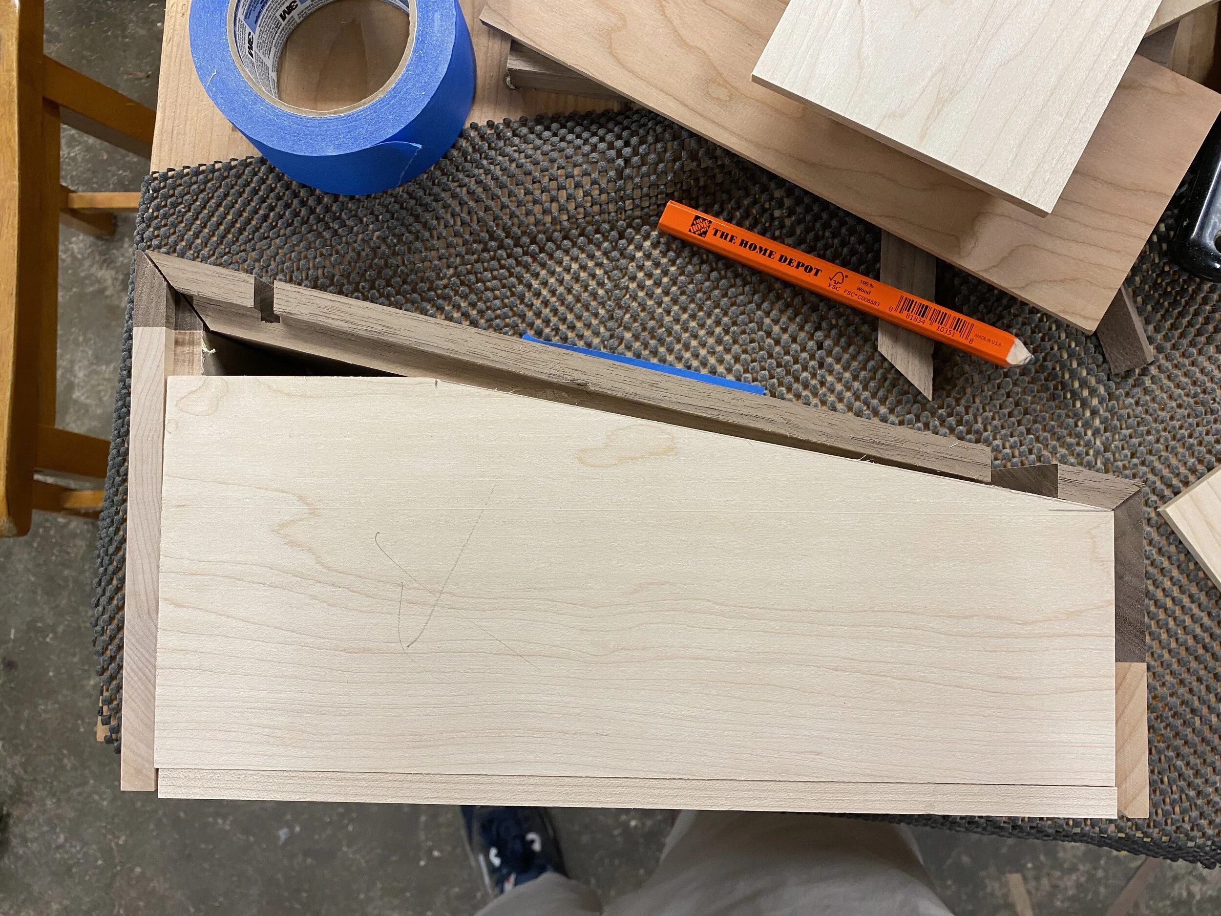
On to the shelves. The basic idea was to slot them together, pretty straightforward. You can see the two slots in the first picture, it was made by raising the blade on the table saw to half the width of the board, and running the shelf through attached to a sacrificial fence on the miter gauge. The top board is the skinnier cherry riser, and then there’s the walnut first shelf. Getting the first notch right on everything was pretty critical: I needed the shelf to be level, and I needed the supports to be parallel. Lot of test fits and sample pieces were made before actually making cuts. I messed up at least one of the supports and had to make a new one.

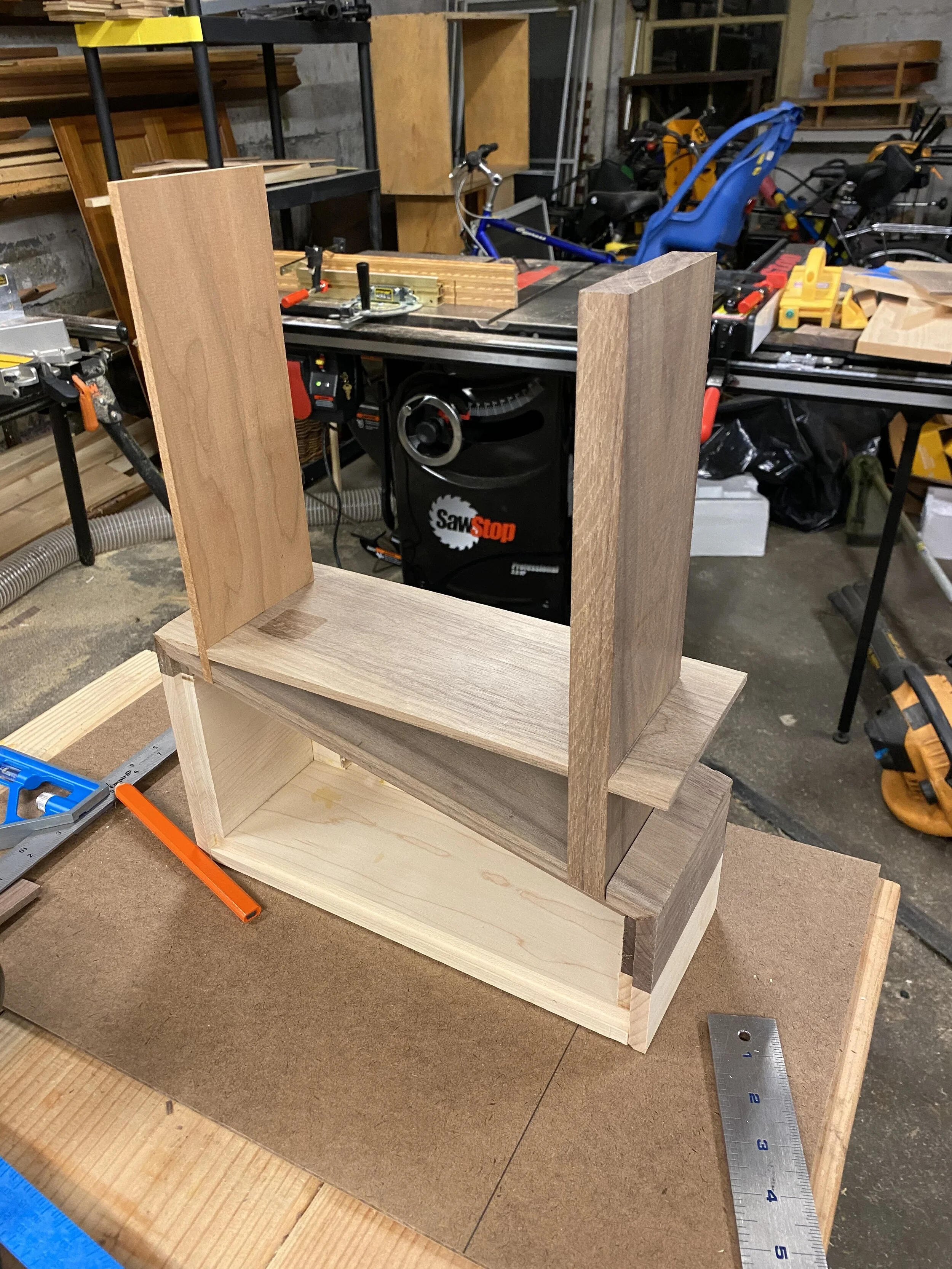
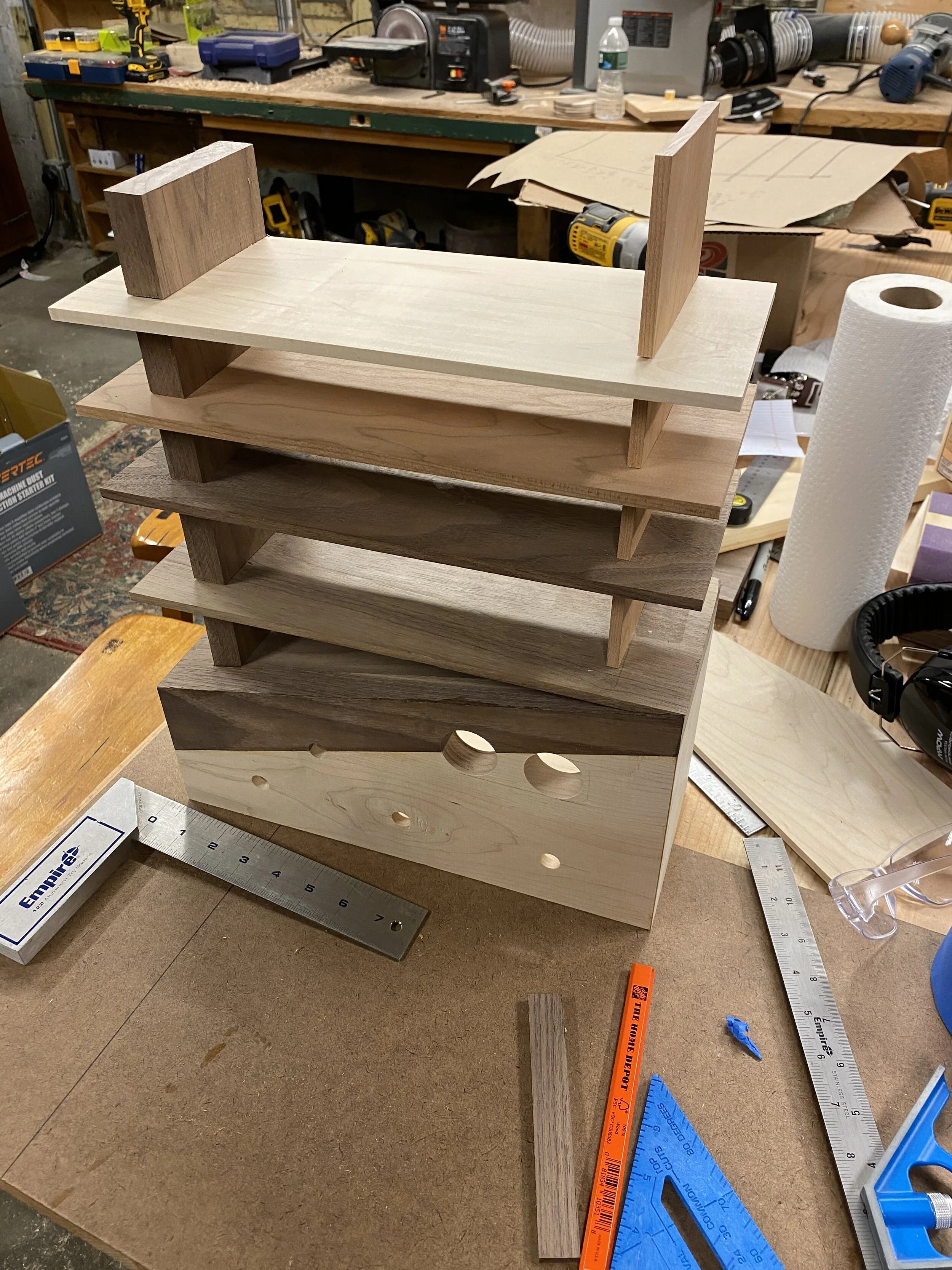
Here you can see how I made sure all the shelves had slots exactly the same distance apart: I taped/clamped them together, and ran them through the table saw like this. I did the supports in a similar way. Next, I dry-fit everything together, and I could finally see roughly what things would look like! Pretty neat, although this was the point where I realized I didn’t want the right supports taller than the left one, and I didn’t really want the shelves to be the same length (they weren’t in my original drawing, but I was unsure of what it would actually look like).

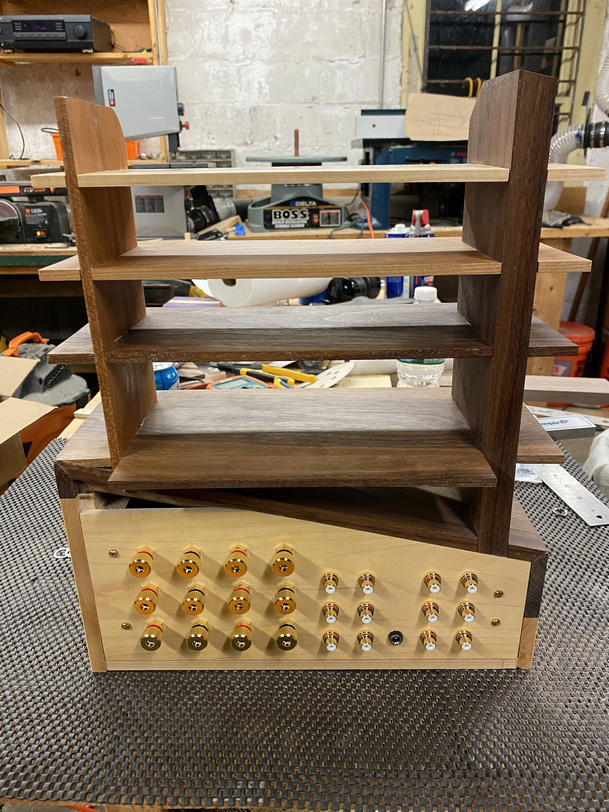
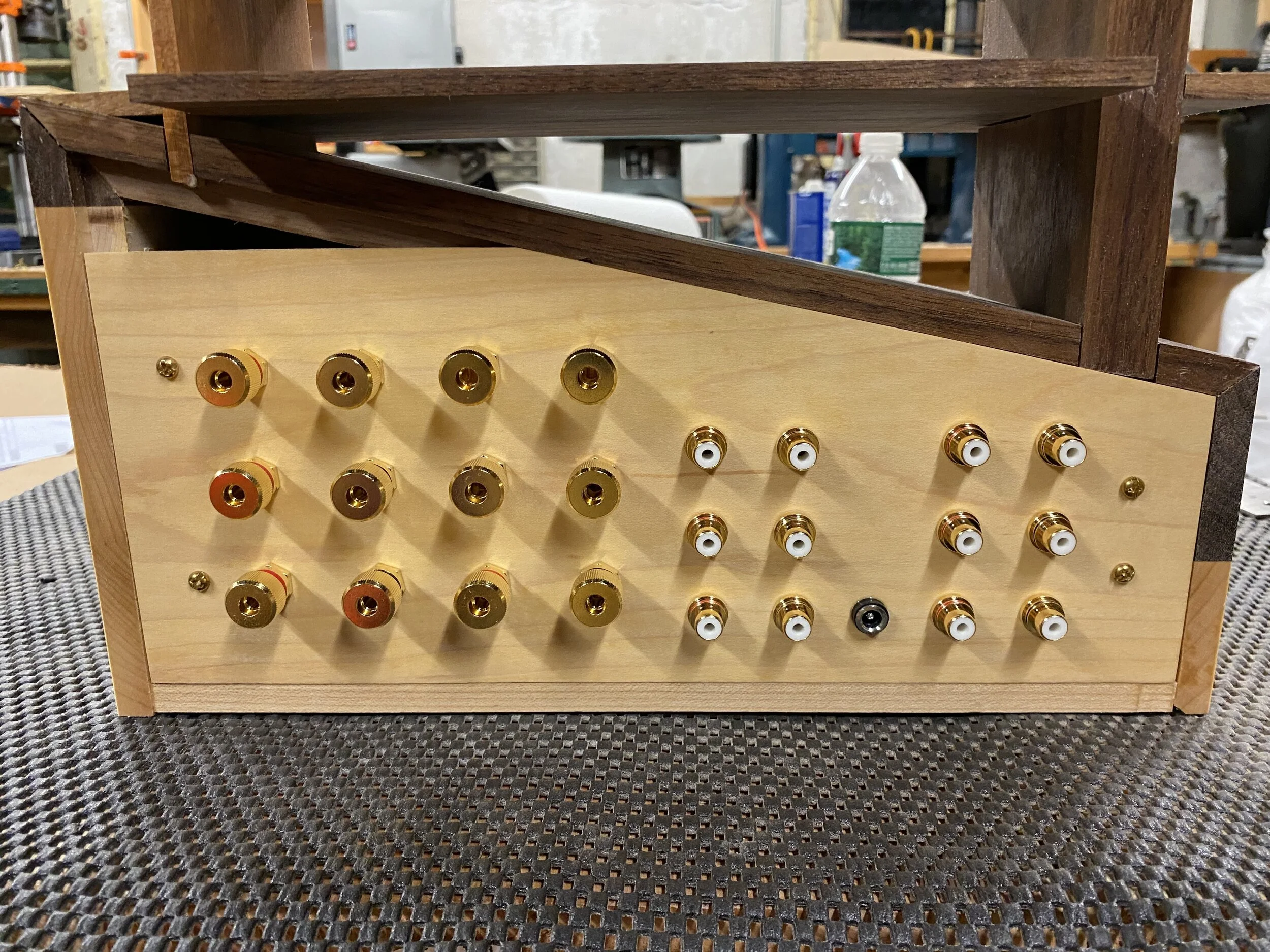
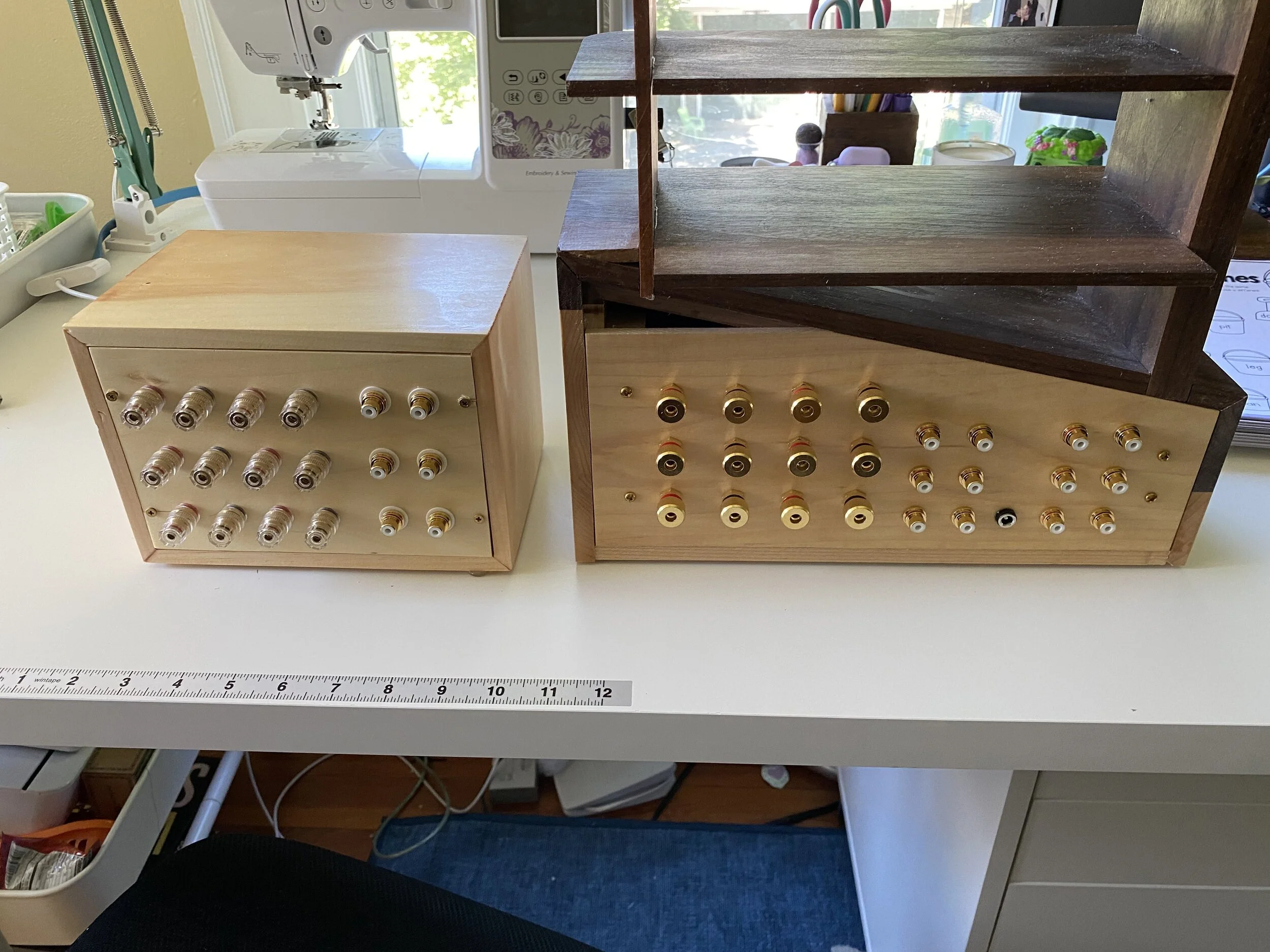
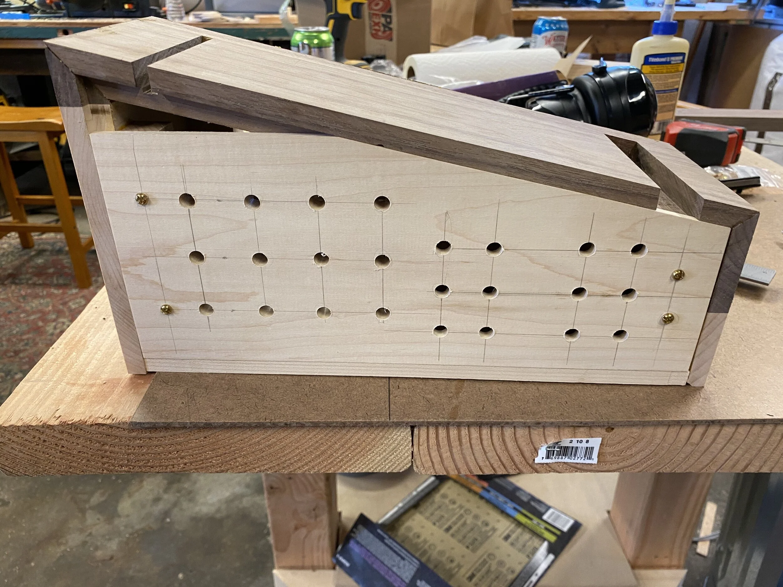
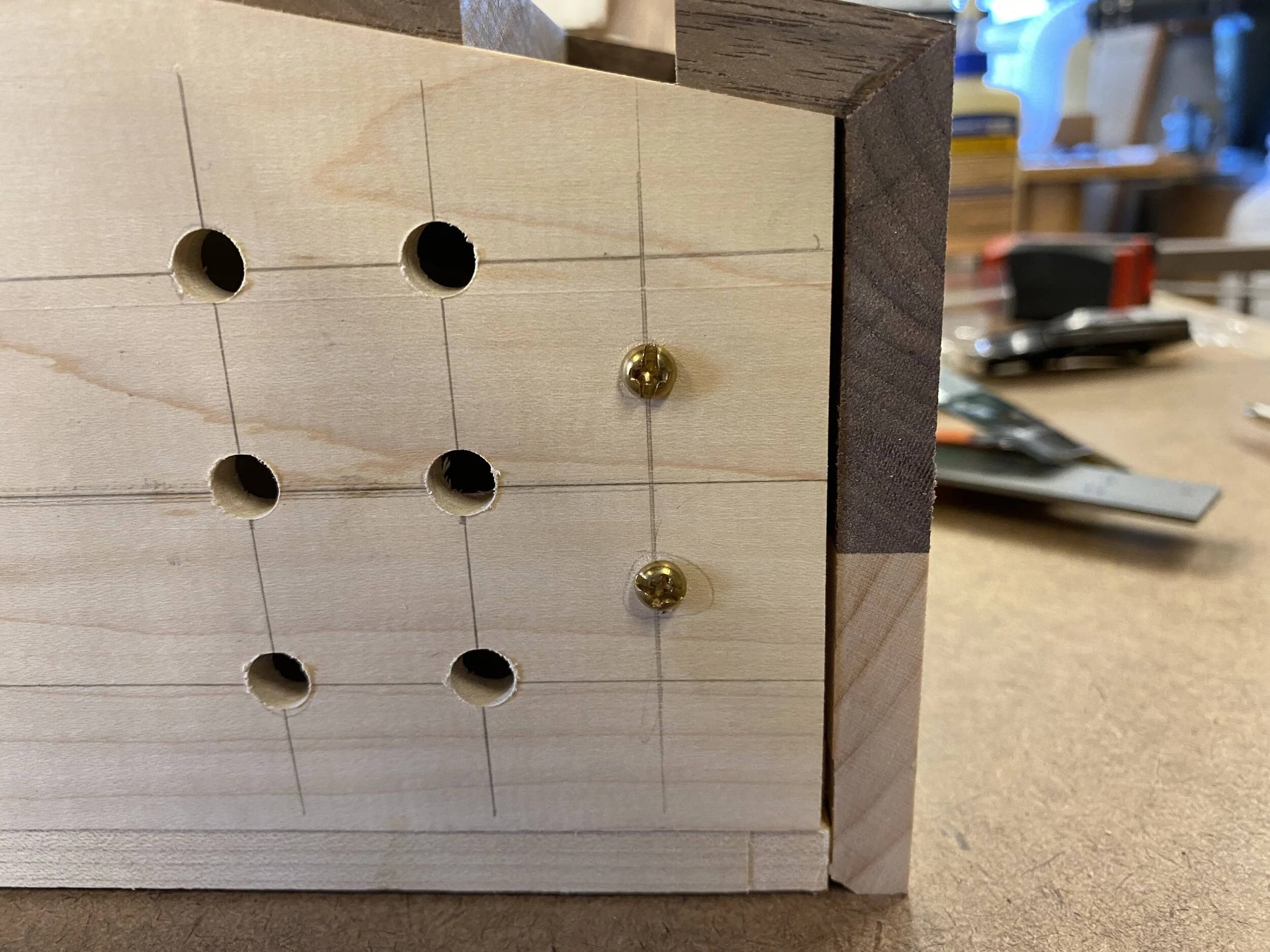
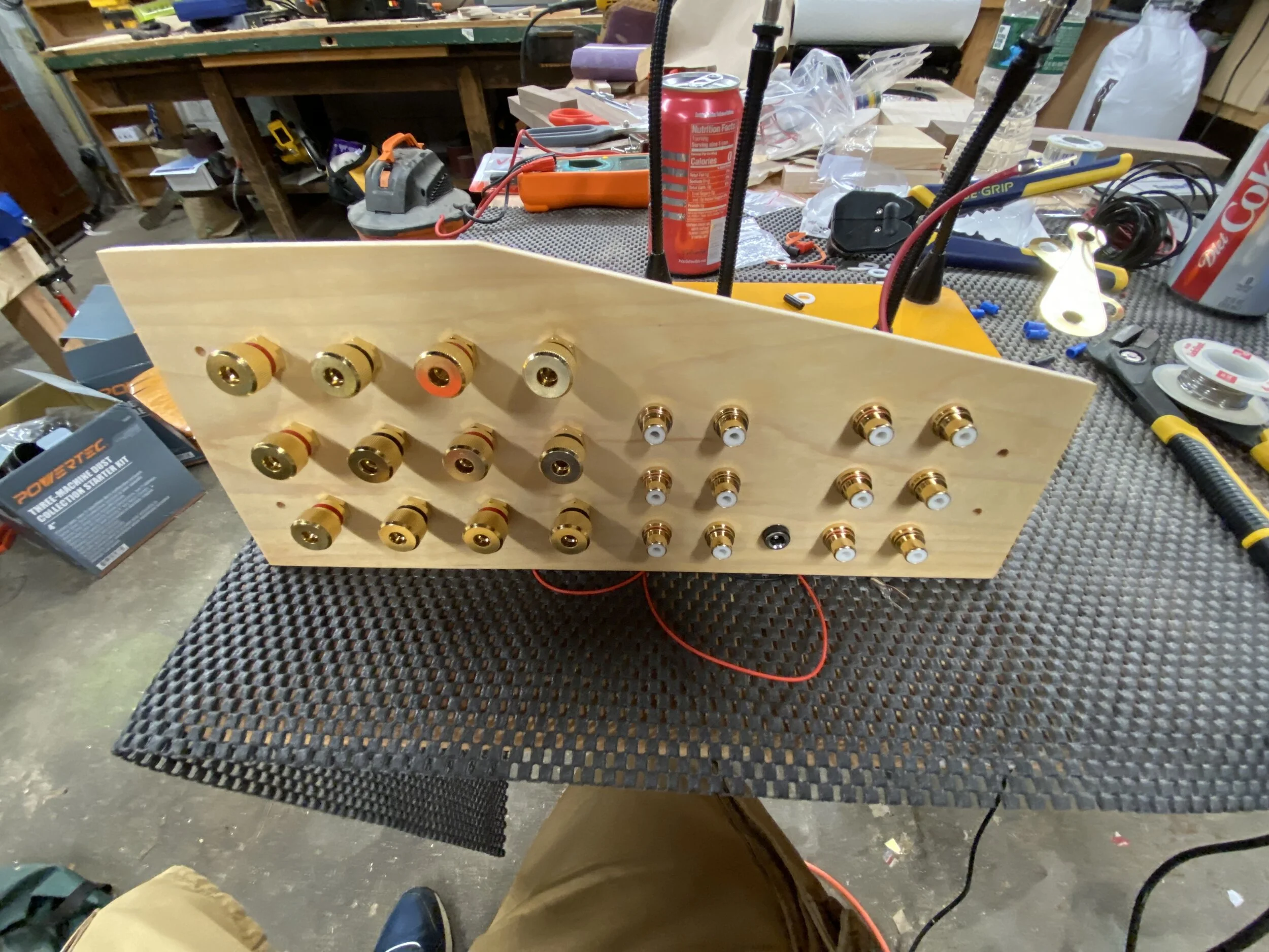
Before I glued the shelves on, I wanted to get the back plate taken care of. In the first picture, you can see how I messed up measuring the first back plate (look at the top edge). I left a gap up top because 1) the wood wasn’t tall enough without gluing 2 pieces together 2) the VU meters have a little circuit board and I wanted to let it vent without drilling vent holes 3) it’s the back who cares. I measured the 2nd one right, but mis-drilled the holes. The third one I got right, you can see that below. In the last pic, you can see how it attached: brass bolts. behind the bolts, there’s a strip of wood with a t-nut on the back side. There’s a picture later where you can see that. For those mounting holes, I positioned the back plate in place, held it down with tape, and then with the whole box on the drill press, drilled the holes so they’d line up perfectly. I had to enlarge the holes on the box side to accommodate the t-nuts, but at least I knew exactly where that hole should be. One other little note is that I noticed my binding posts actually had longer shafts than would work with 1/4” wood (that… that’s what she said?), so for the 16 holes on the left, there’s a 2nd piece of 1/4” maple glued to it to give it enough depth. Also at this point, I had forgotten about the hole for the DC jack for the VU meters, and in fact, didn’t remember to drill it until after I had already put finish on the back. Ah well, it’s the back, it doesn’t really matter. Once this was drilled out, I sanded it and threw on a few coats of Danish Oil.

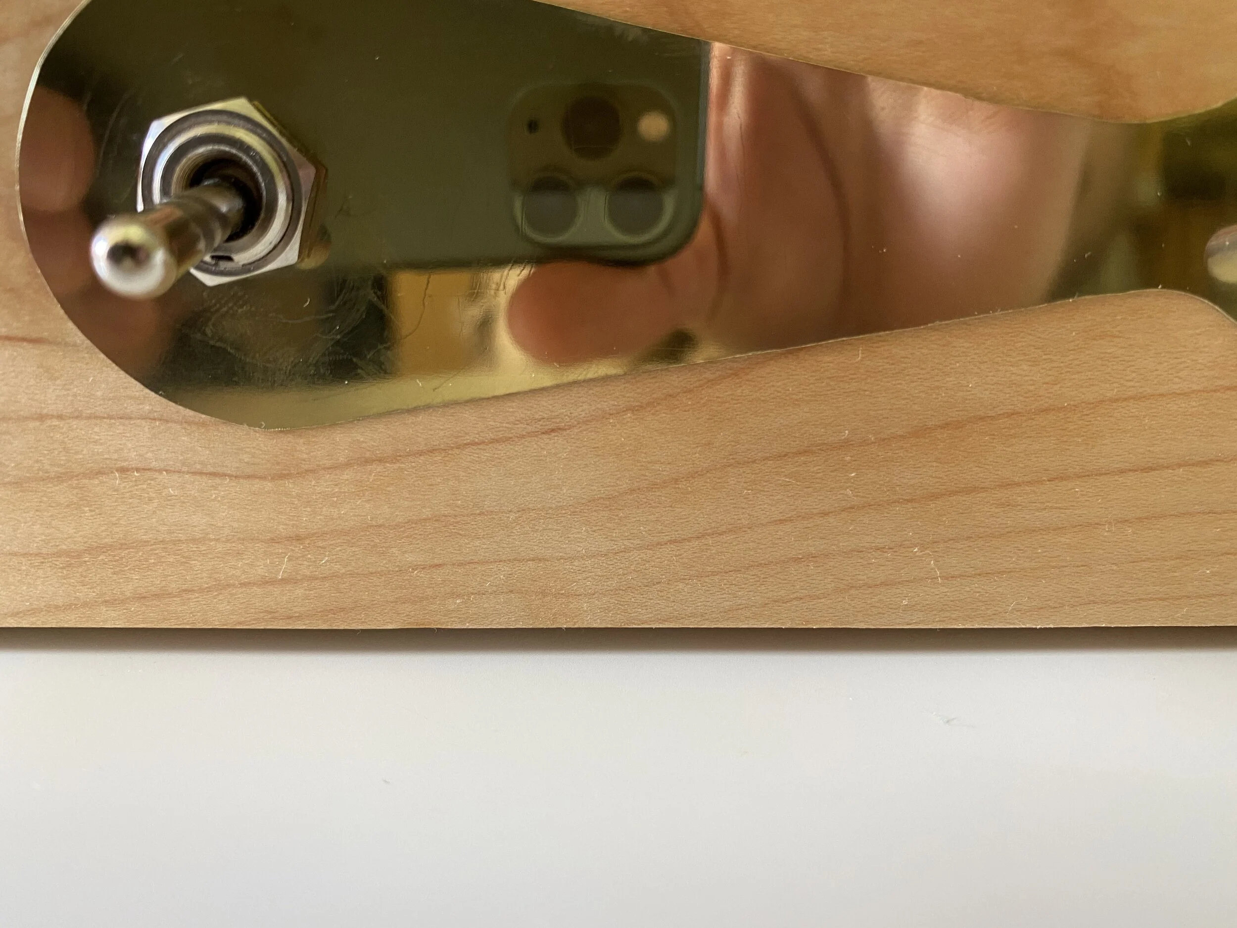
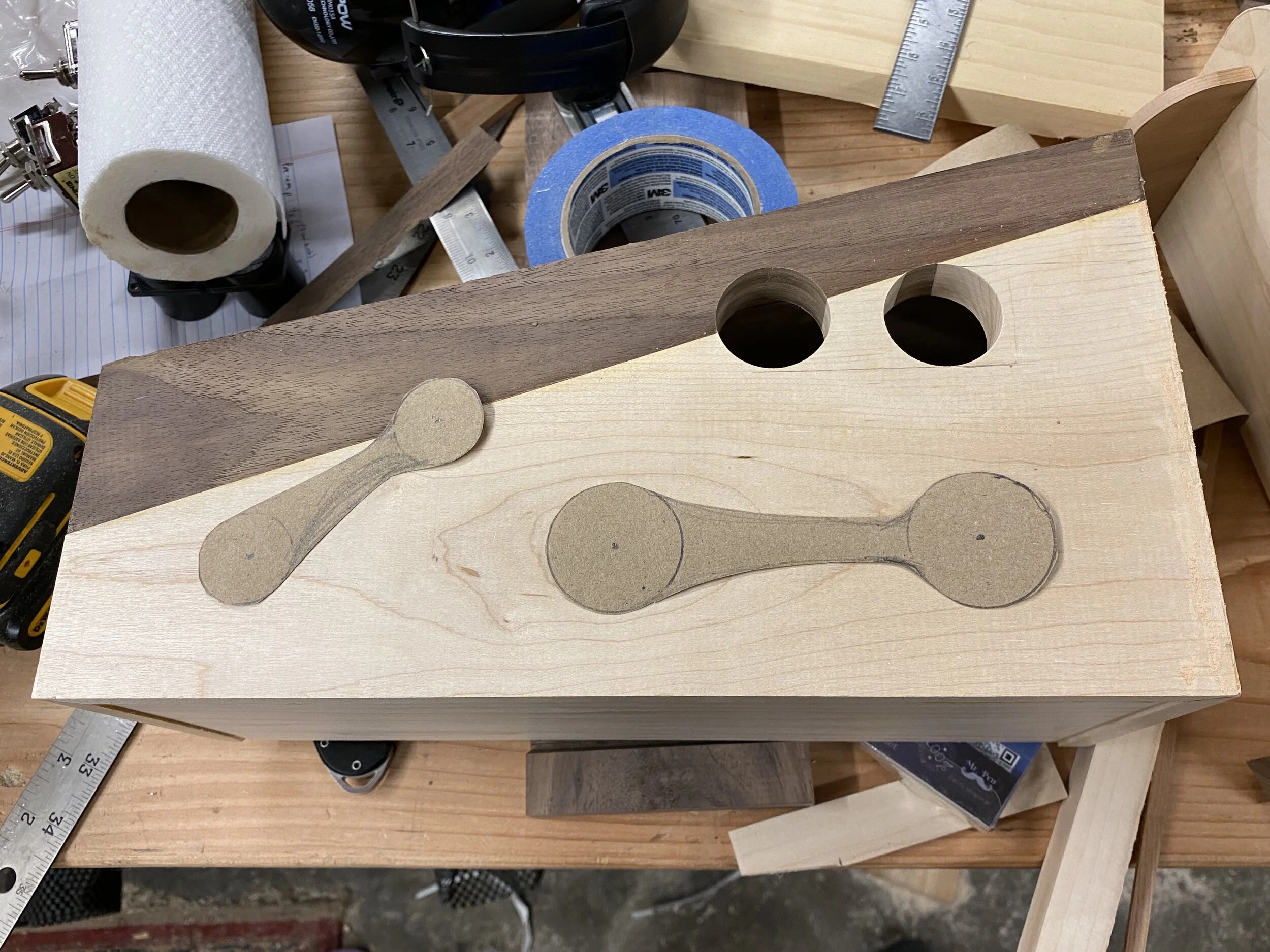
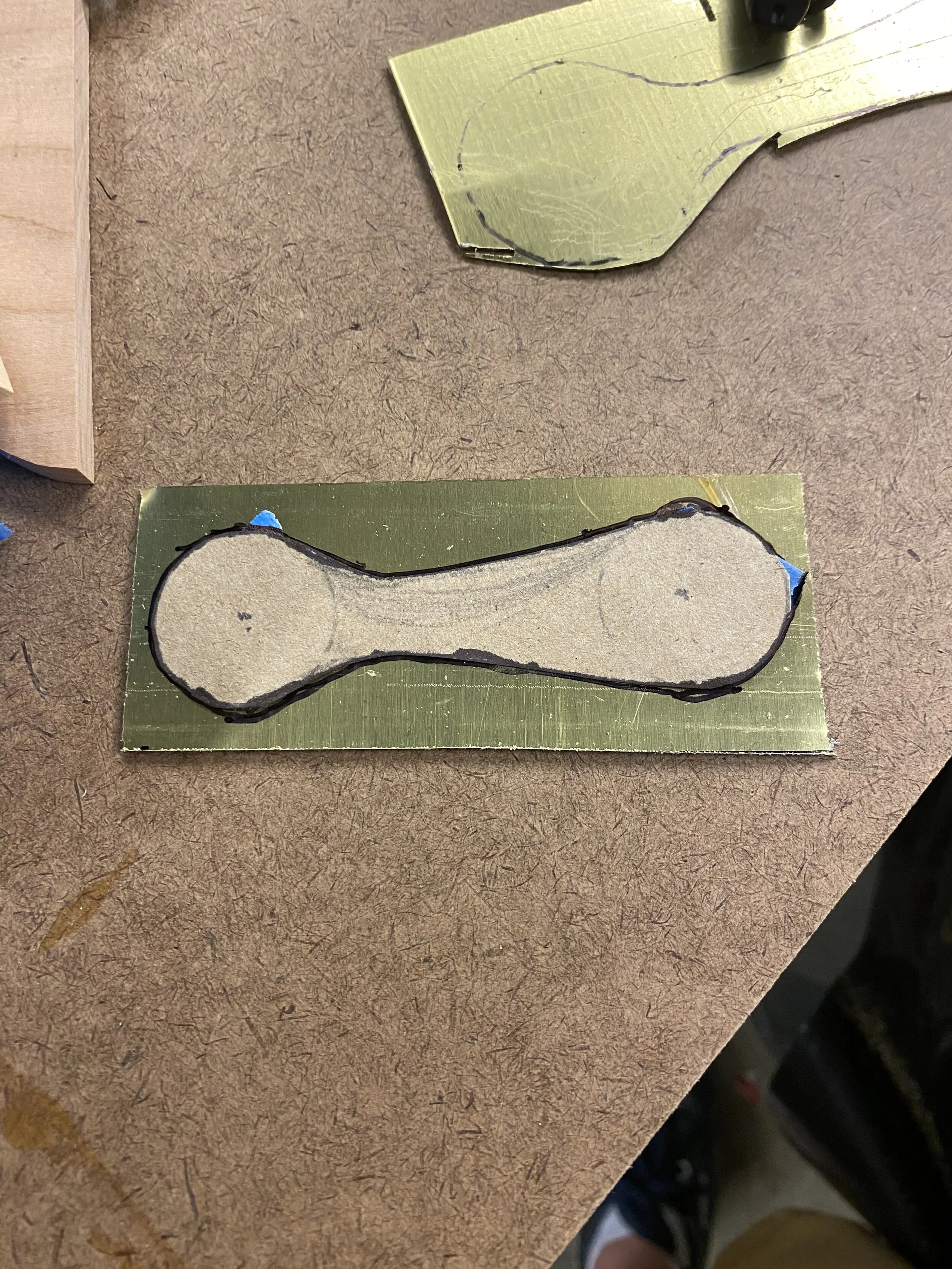
The brass accents on the front were a real pain in the ass, mainly because I don’t have any good metal working tools. I tried cutting it with a jig saw with minimal success, and then sanding it into shape on the bench sander/spindle sander. The sheet brass I had on hand was also on the thick side, so sanding took forever, the work piece would get hot from the friction, burn my fingers, and at the end, it didn’t even fit because I had mis-measured by 1/8”. So, I got some thinner brass, taped it to the particle board to give it some stiffness when cutting, rough cut it on a scroll saw, and then sanded it, which worked better. I made these at least 3 times before I got it right, but once you’re this deep into a project, another few hours burned on mistakes is worth it.
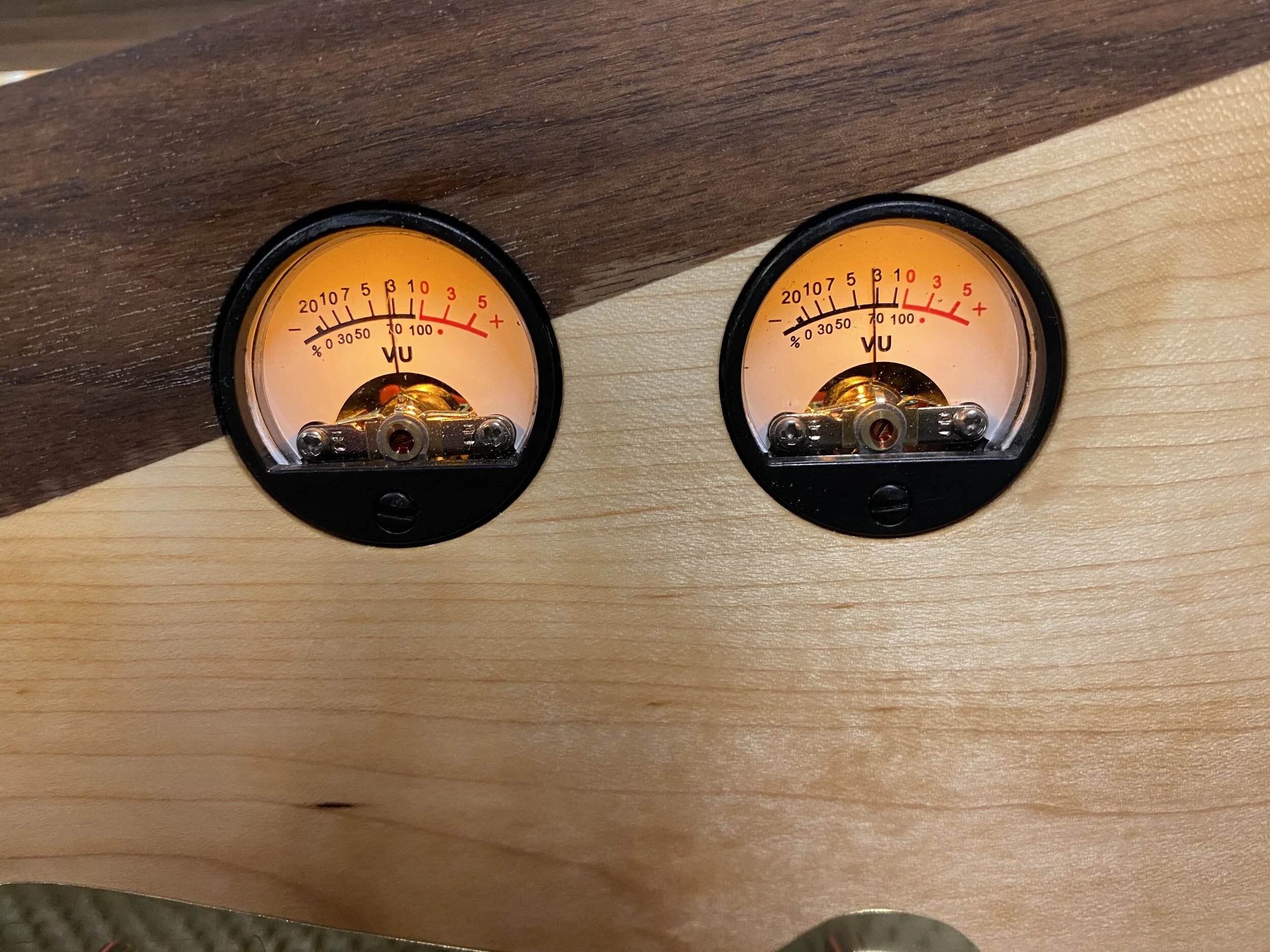
Continuing with the face, I started to think about the VU meters. Originally, I had planned to seat them on top of the face, with the square mount visible, but I realized I could have them just showing the circular face. I perhaps should have hollowed out the back like I did for the switches, and then attached them with screws, but it was too late to do that now that the box was glued (no way I was getting a router in there). So, I just sanded off the mounts on the bench sander, and press fit them in. In the 4th picture, you can see an unsanded one, and then the press fit one. I was slightly worried I’d damage the innards with the vibrations from the sander, but they seem to work fine.
A digression about these VU meters: They came with literally 0 instructions, just a bag full of meters, wires, and a circuit board. I was able to find some advice on what terminals on the back mapped to what. They had the signal inputs and the DC power inputs, and I… really didn’t want to get them messed up. Luckily, my googling was successful, and they worked great!

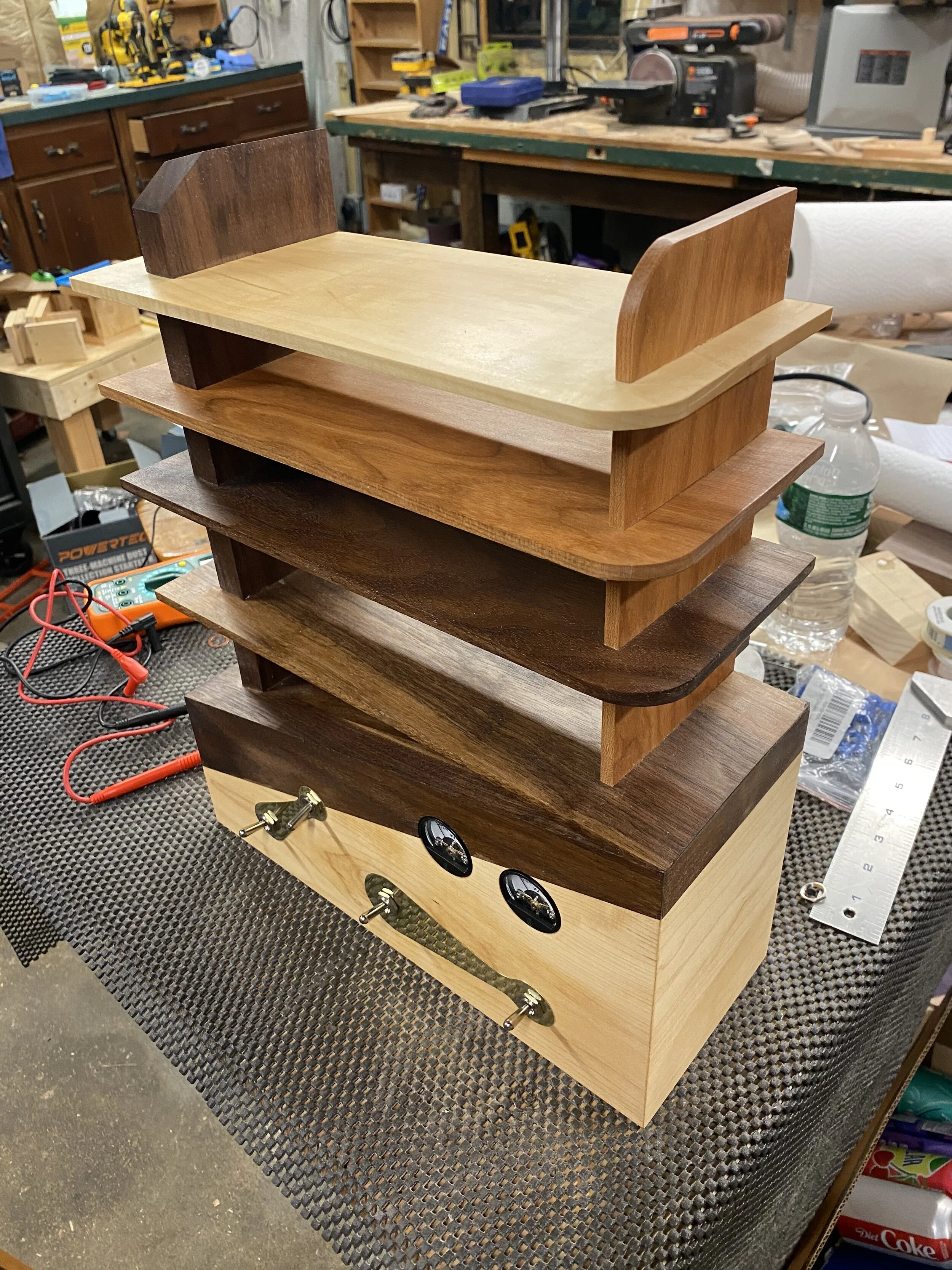
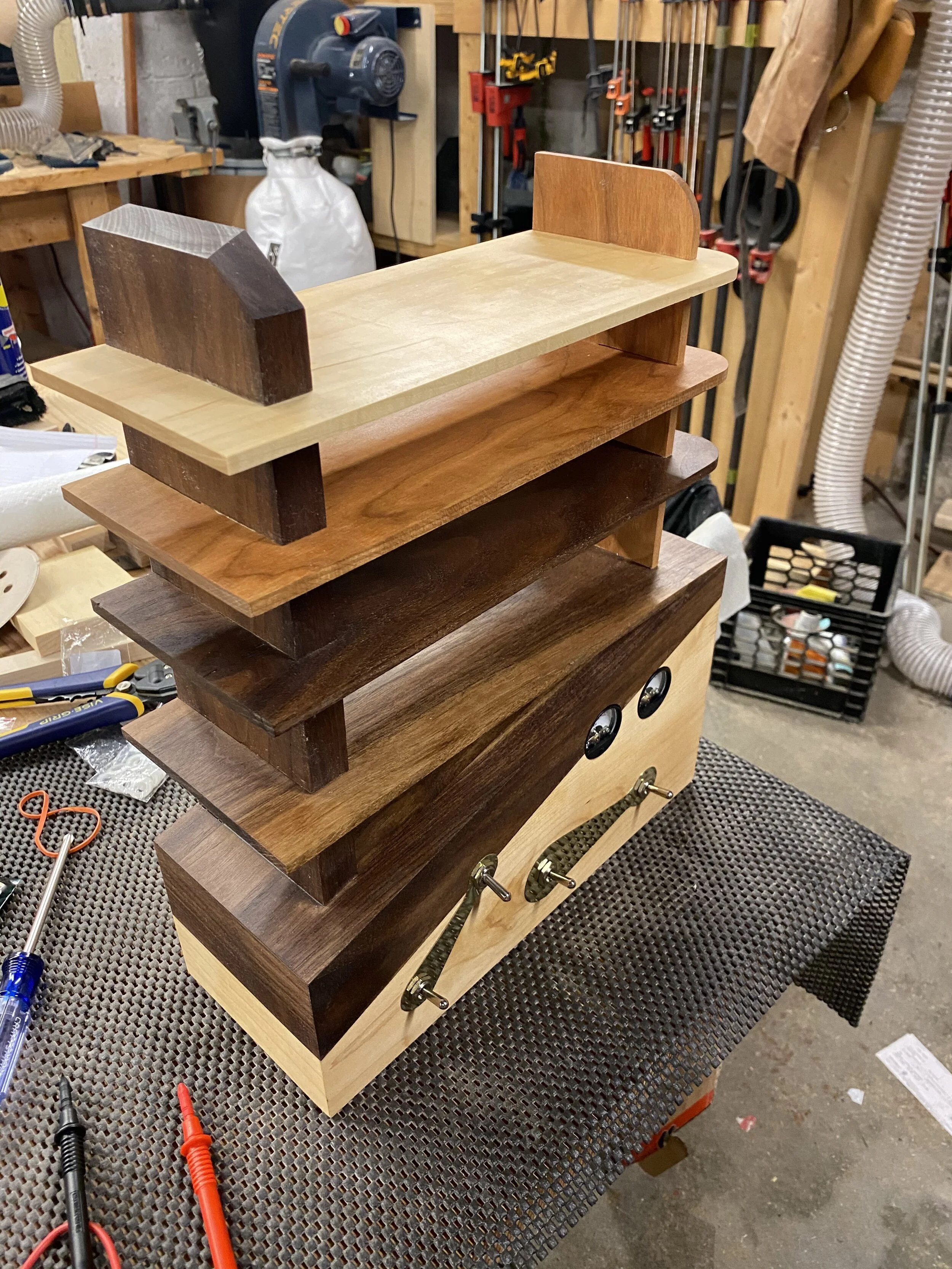
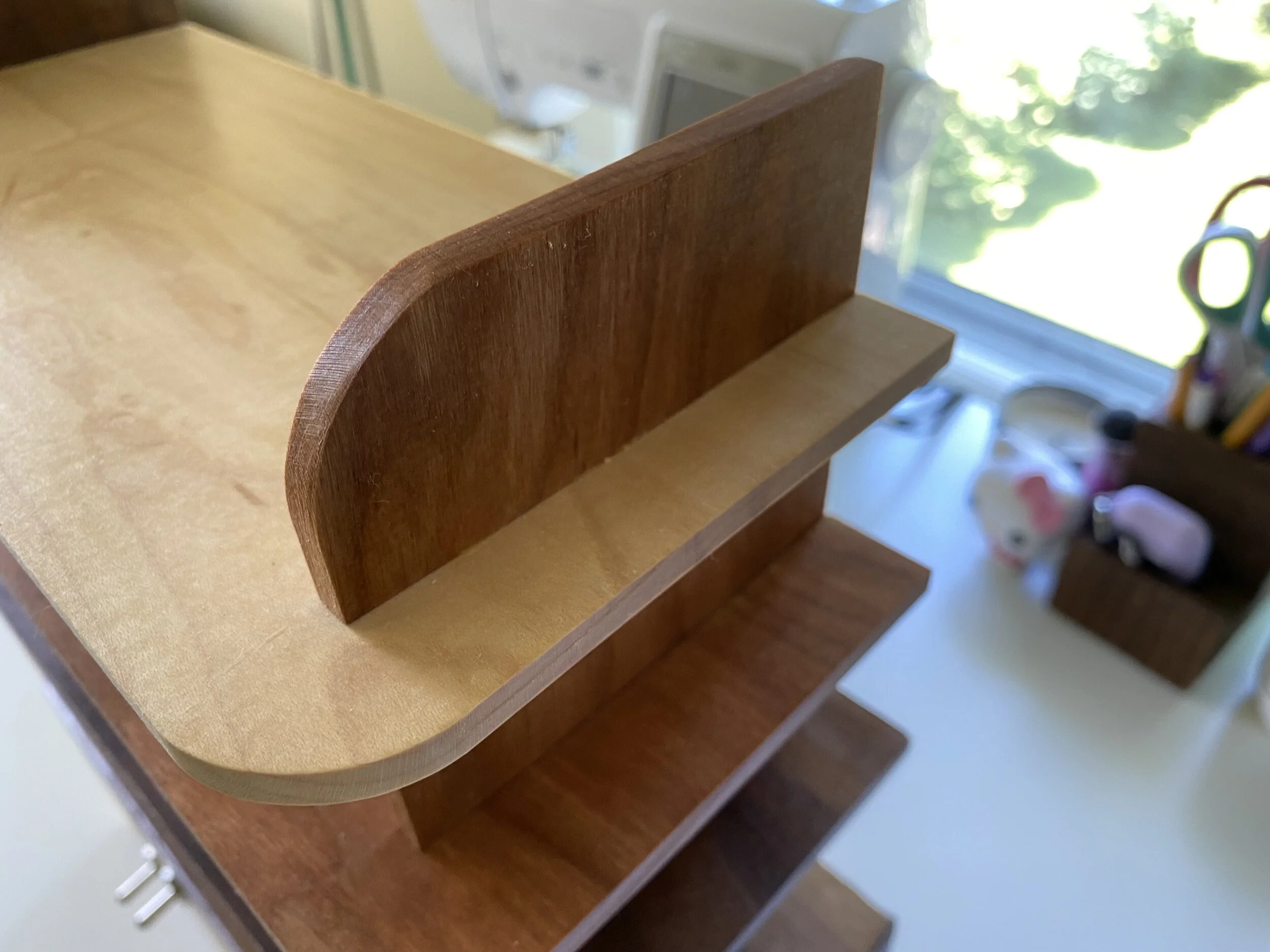
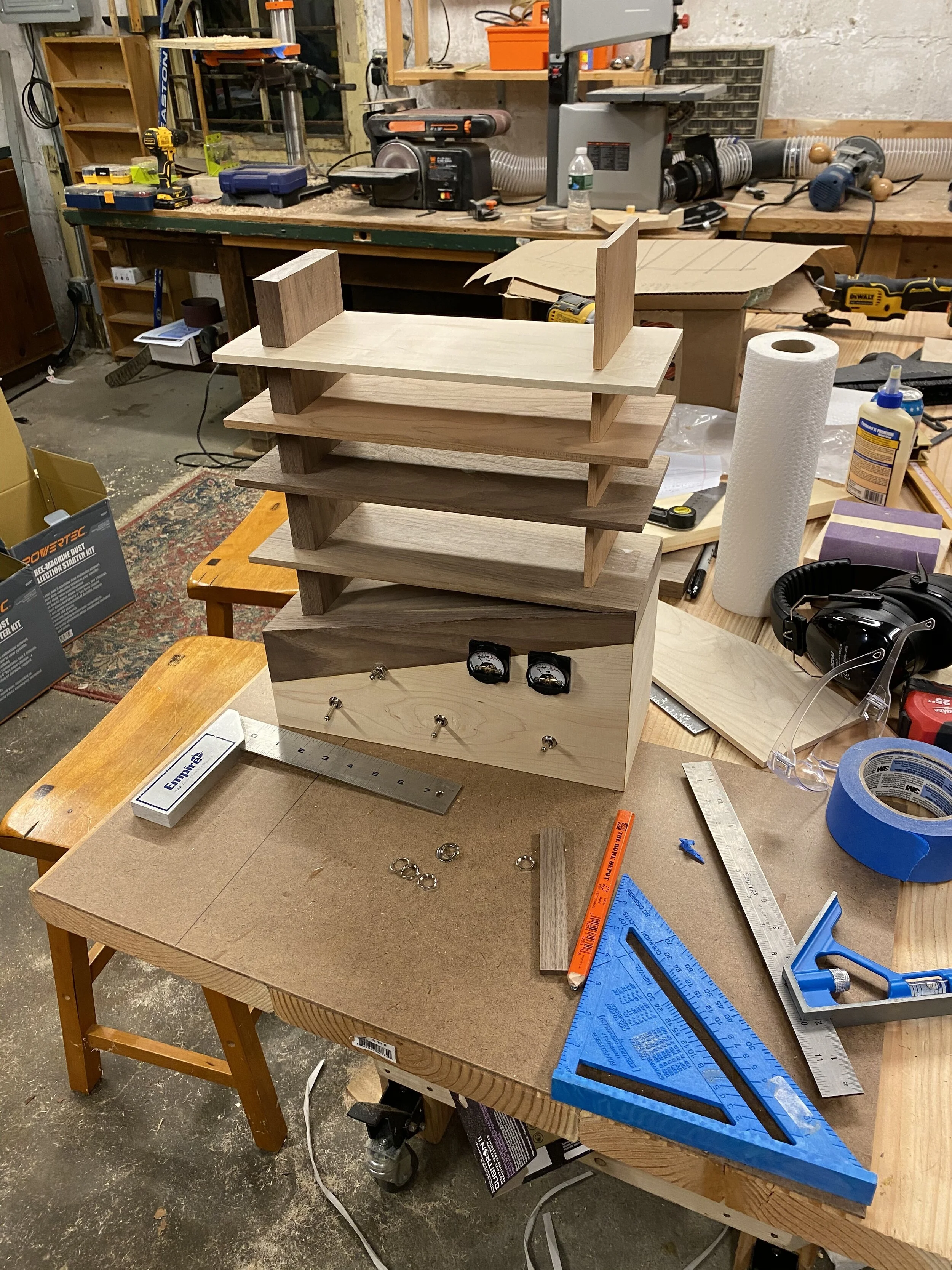
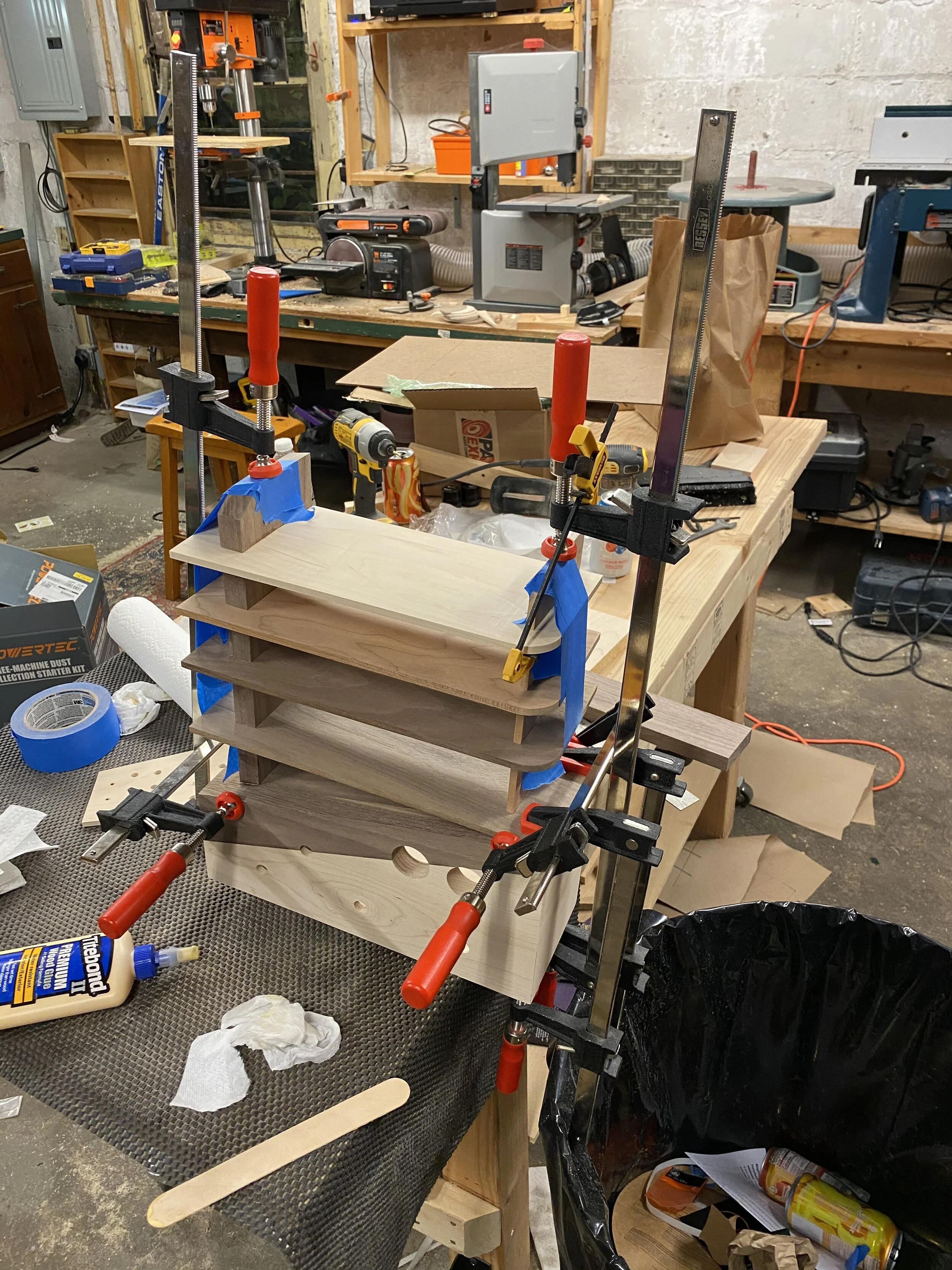
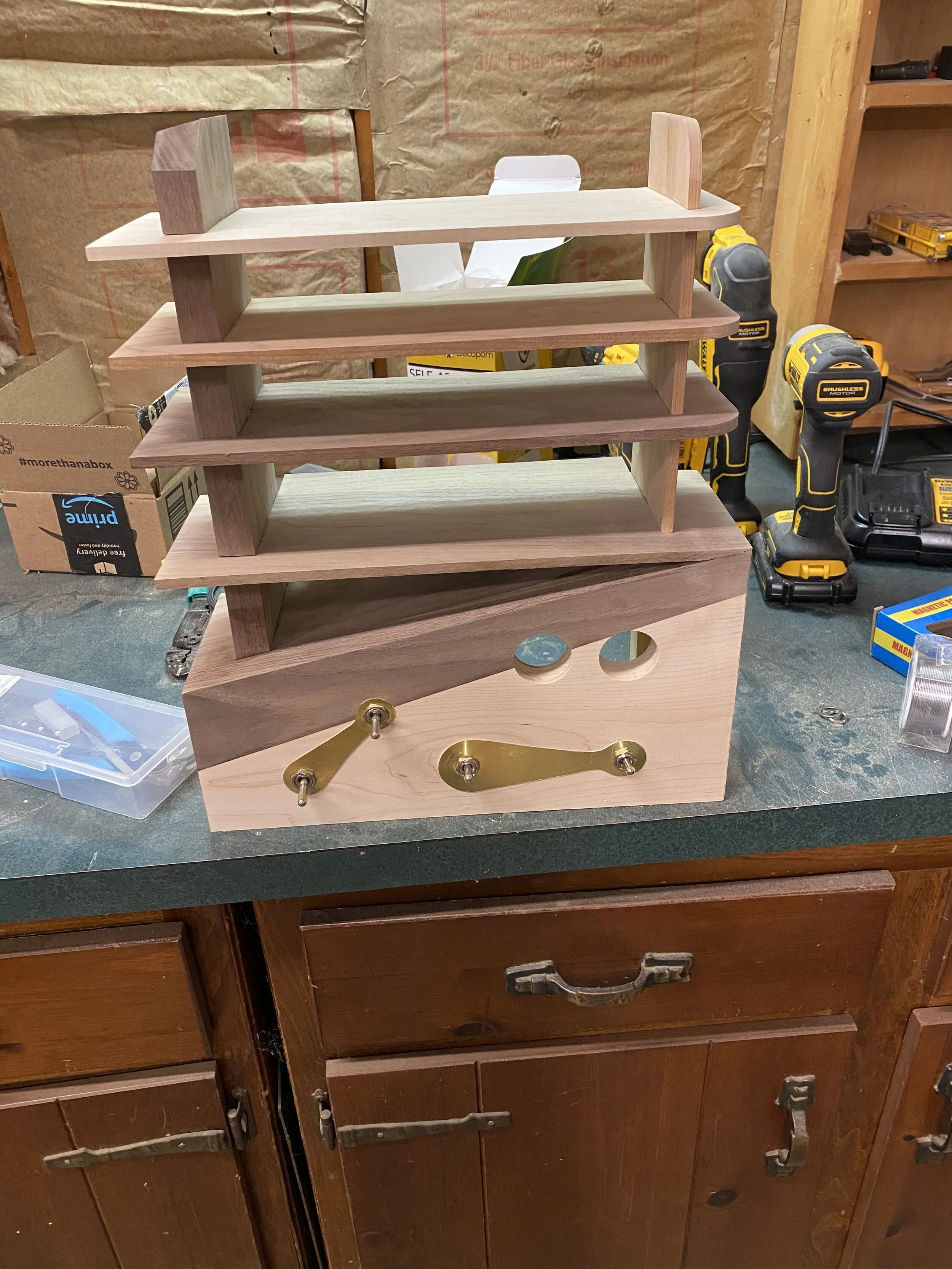
Next it was time to glue the shelves in place. I sanded the main box and the shelves before gluing, since I wasn’t going to have great access to all the nooks and crannies once I glued everything together. I had also made 4 adjustments at this point: first, I cut the shelves progressively shorter as they went up. Second, I rounded corners on their right side. Third, I shortened the cherry support, and rounded that one off as well. I took a few passes, only taking a little off each time, because I really didn’t want to have to remake everything. Same thing for the thicker walnut support: I gave it some nice sharp angles, only taking off a little each time. The angles match other angles found elsewhere on the box. Finally, I had added a strip to the back of the bottom most shelf to give it more depth, as the pre-amp that was going to sit there was deeper than the box. I knew this ahead of time, and figured since it was in the back, it would be fine. I was right. The tolerances on the interlocking grooves wasn’t perfect, and I wanted the shelves to have no visible gap on their top face, so I used tape and clamps to pull them up. Once the glue dried, I could put the switches in with the brass plates, and get a pretty good idea of how it would all look!
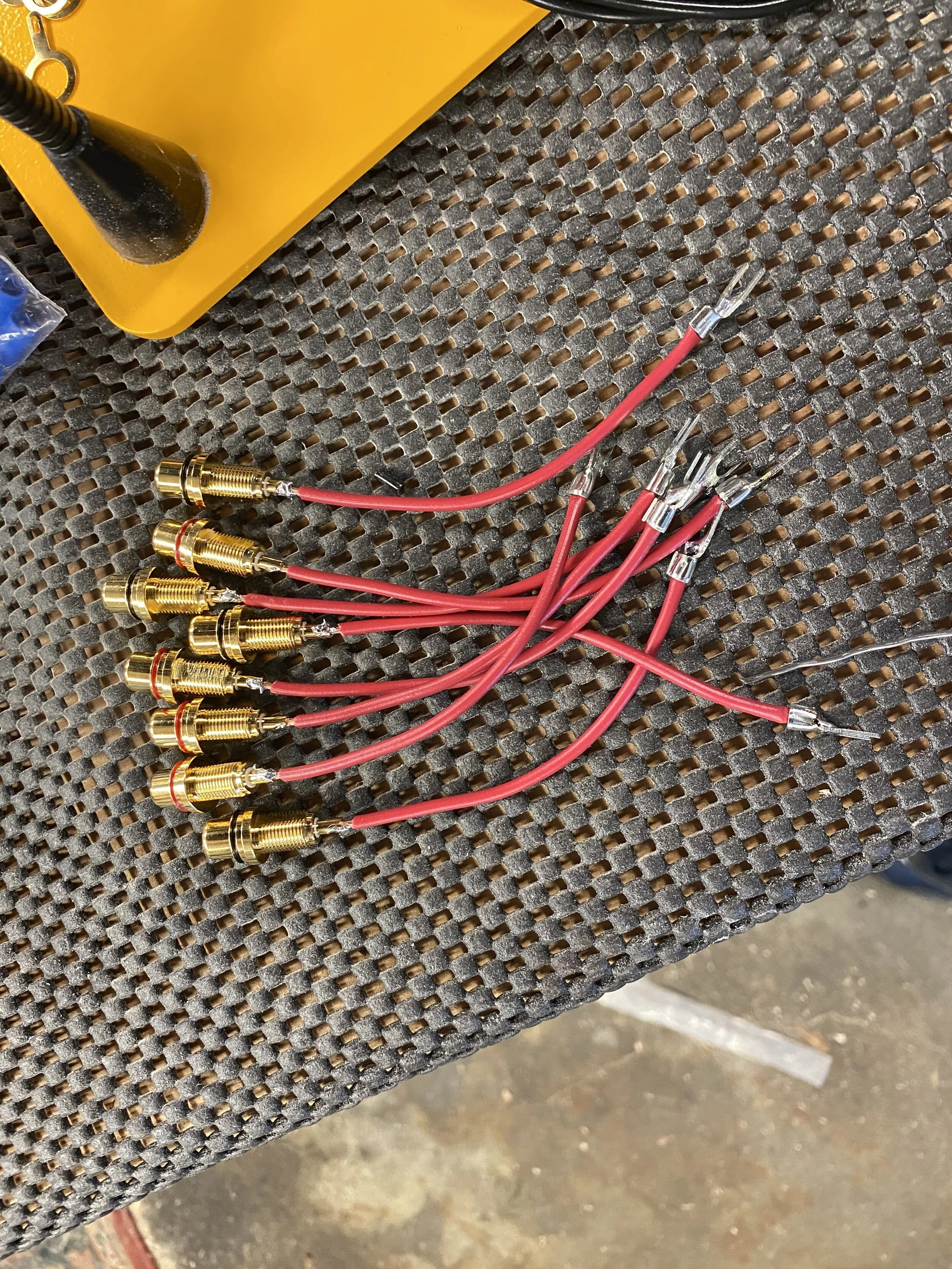
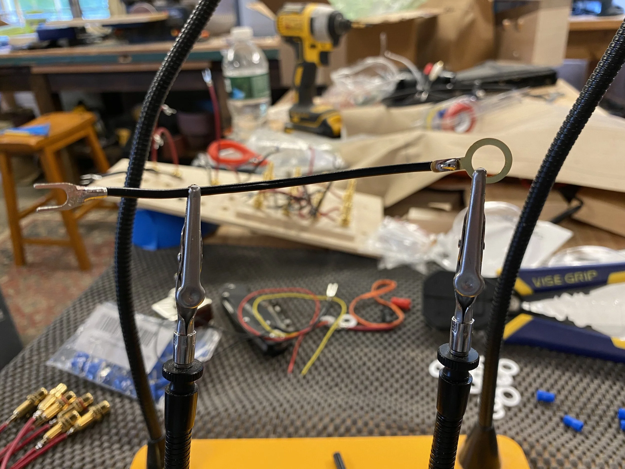
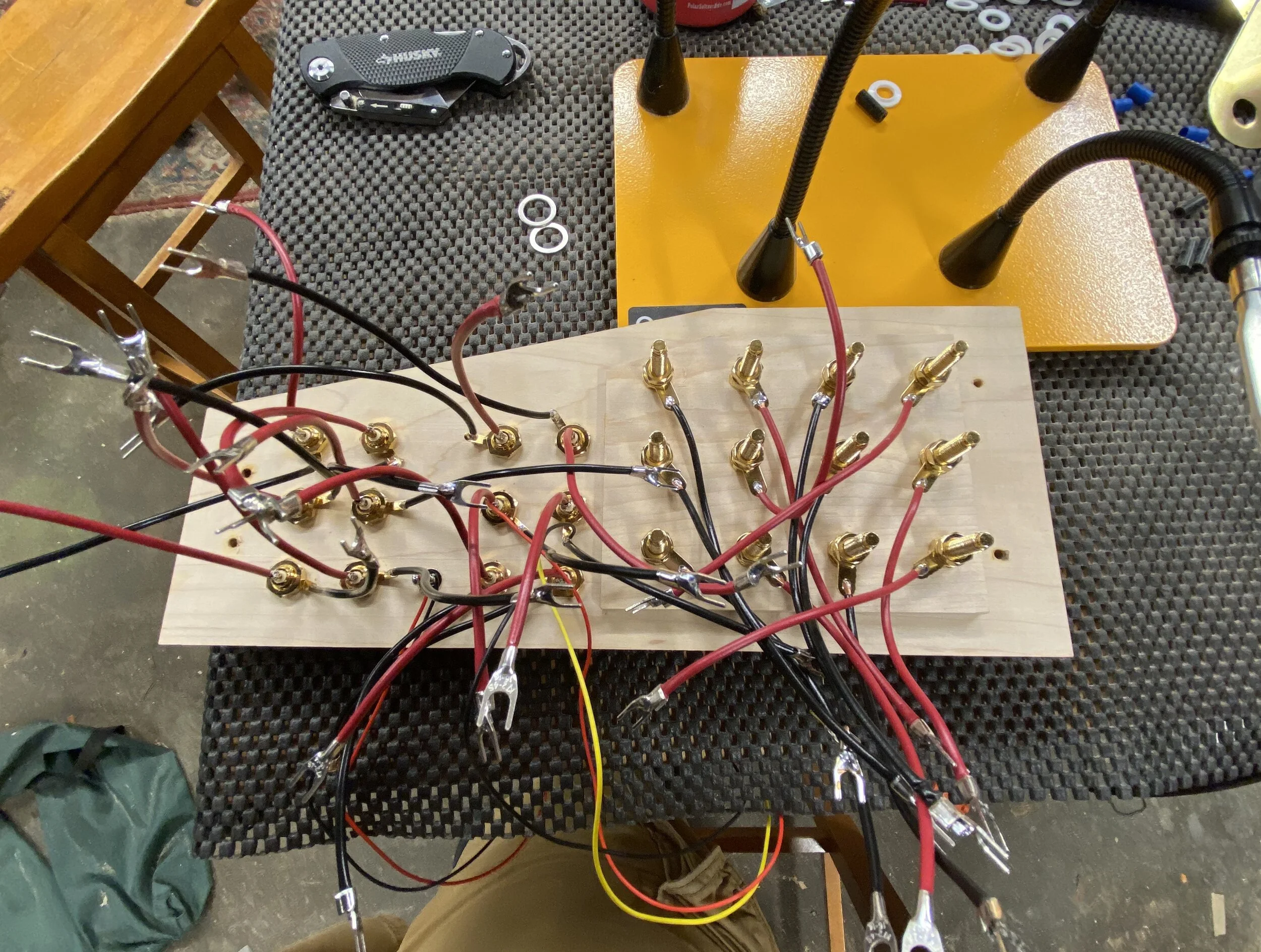
The wiring was my least favorite part of the first switch box, so I saved it for last (also, it kinda logically comes at the end). This time, with even more wires, I wanted to make it as easy to connect stuff as possible, so rather than try to screw bare wires into the screw terminals on the switches, I soldered on spades to the ends. I had a set of helping hands, which were alligator clips on bendy metal poles, and that made this a lot easier and less burny on my fingers. The back has a lot of brass and I’m pretty pleased with how that looks. The input for the VU meter is attached to the middle set of RCA jacks, which all the input will run through, so no matter what source or amp, they’ll get a signal. They turn on and off, including their backlights, with the simple on/off toggle swtich. Attaching the spades was definitely a much easier way to connect the switches.
And now for a digression about 4PDT switches: they’re not off/on switches, they’re on/on switches. They have 3 banks of terminals on the back, and throwing the switch just changes if the top of bottom bank is electrically connected to the center bank. There’s no position where everything is off (although I think you can buy some that do have a middle position). So far so good. The problem is that the connected bank is opposite the position of the switch. By that I mean, if you flip the switch up, the bottom bank of terminals is now connected to the center, and if you flip the switch down, the top bank is connected to the center. It makes sense when you think about how the guts of the switch look: the back half of the toggle is going to be the opposite of the front part, like a see-saw. But, since I wanted the position of the switch to match what was connected on the back (i.e. you flip the switch down, now the bottom input is live), I had the wires cross on the inside. So, the bottom RCA jacks are connected to the top row of terminals on the switch. You can see this mess if you look close at the last picture. Once I had everything wired up, I tested the connections with a multimeter to make sure 1) they were connected 2) there weren’t any shorts that would explode my stereo.
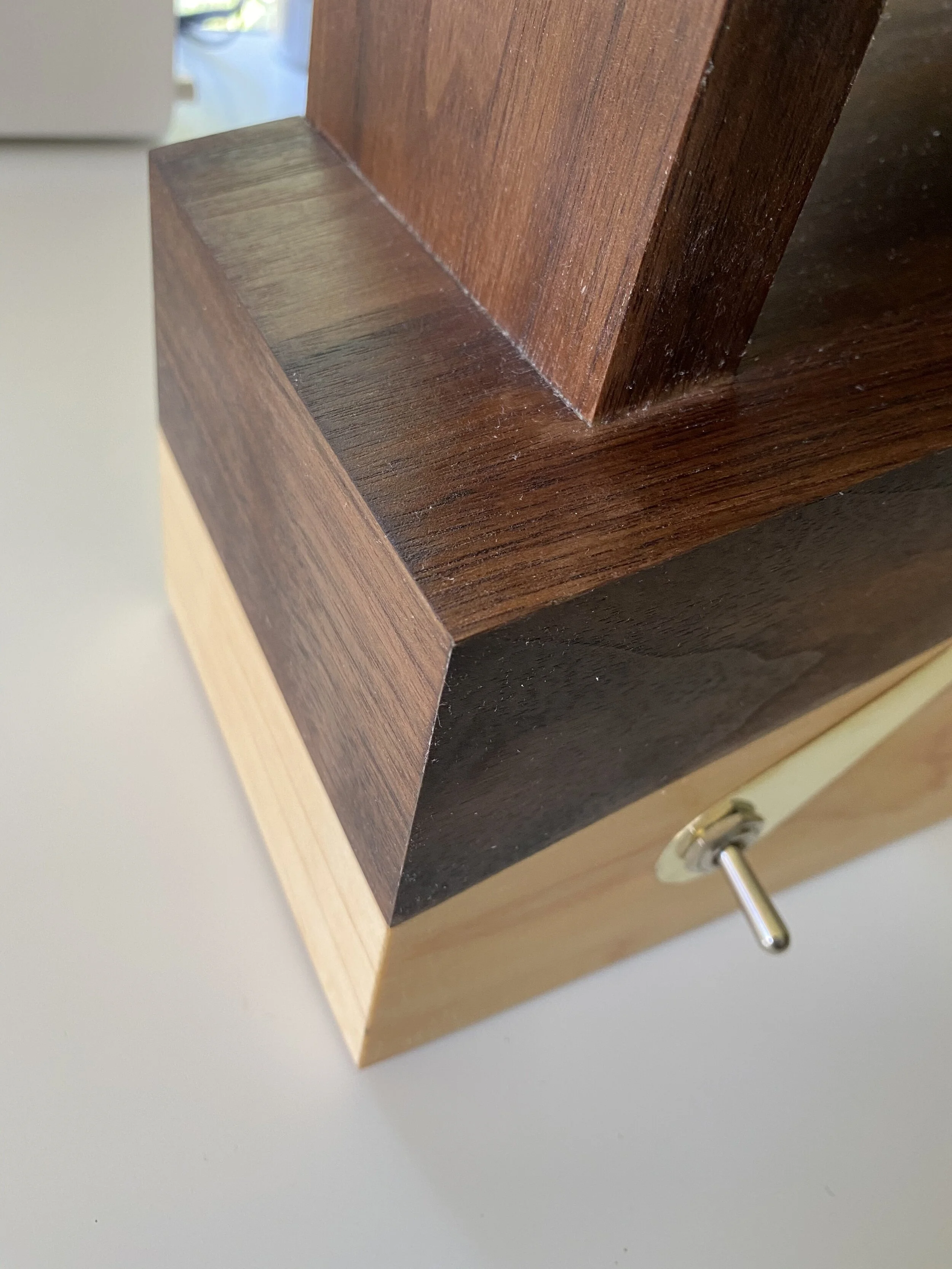
I slapped some self-stick plastic feet on the bottom (here you can see the mounting brackets and the extended bottom shelf). A few coats of Danish Oil, an ill-advised attempt to rub some wax in to bring out the shine, and it was time to shove everything together. In the second picture, you can see the little circuit board for the VU meters, which is held in place by some self-adhesive velcro strips. You can also see a peek of the mounting bracket that has a t-nut in the back. . Screwed the back plate in place, polished the brass, mounted the switches, and it was done!

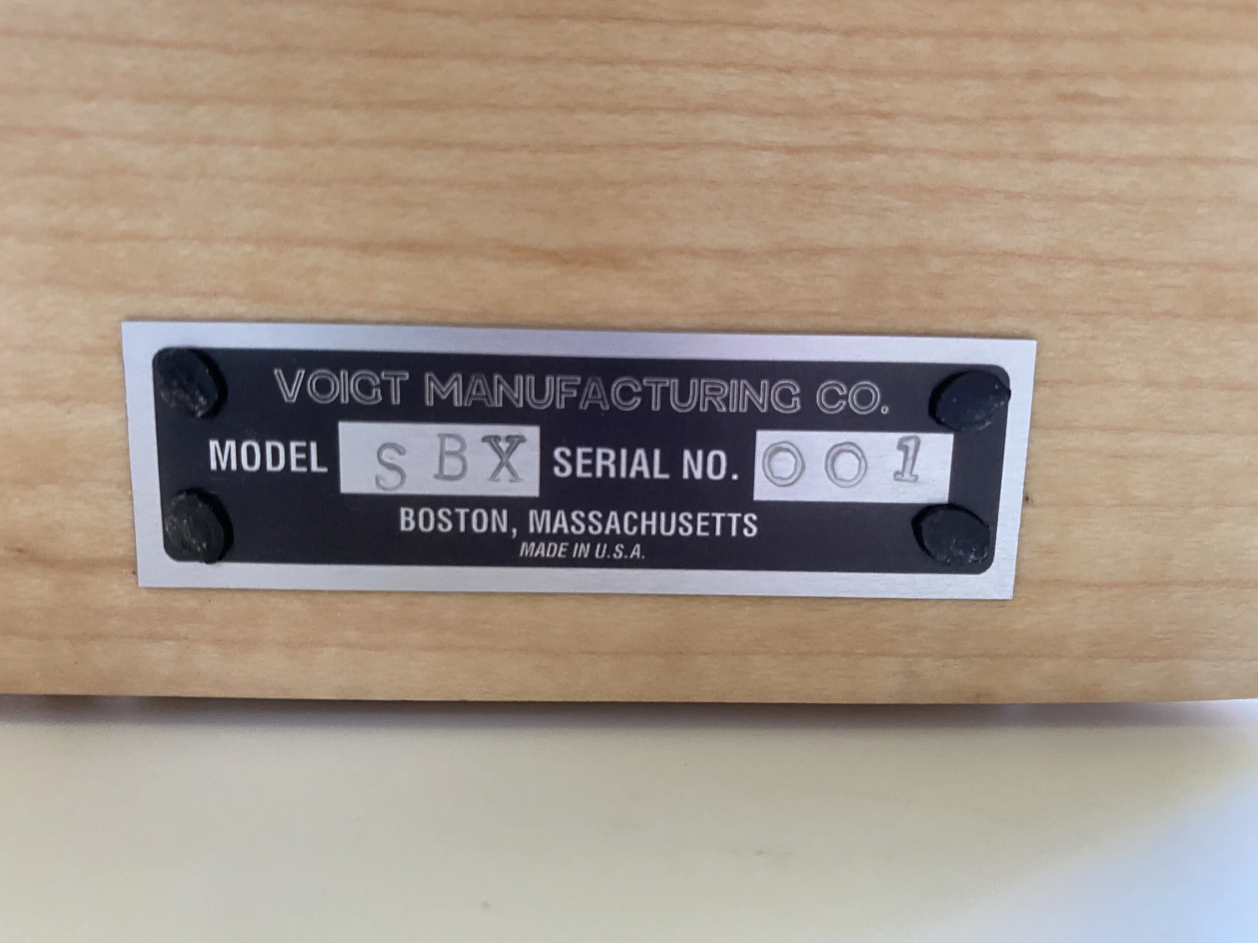
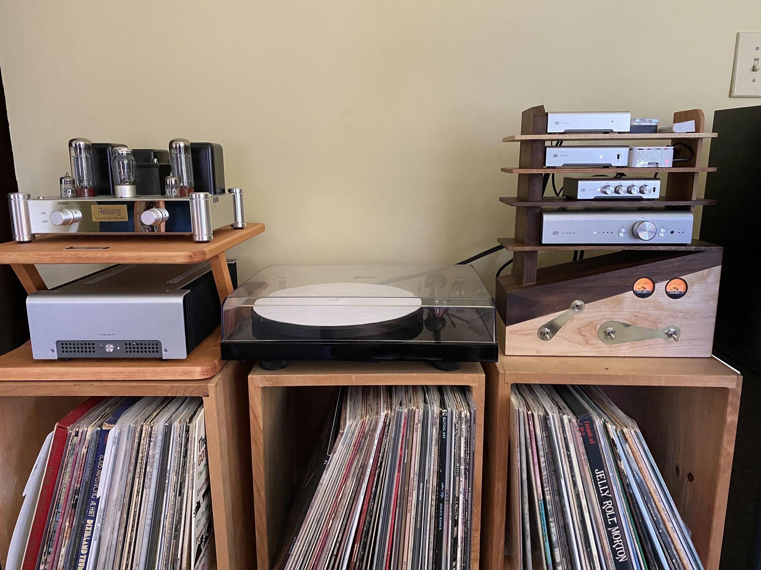
All finished! Here are some mediocre glamour shots! The little “Voigt Manufacturing Co.” nameplate I custom ordered on the internet, and then I stamp them with some metal stamps from a craft store. Still haven’t gotten the lettering perfectly aligned, but I think the akimbo-ness adds some charm. I attach them with carpet tacks, because nothing else fits the holes well (they’re kinda large for the small size brads you’d want to use) and they’re a good color. It’s always the last finishing touch I put on things! And there you have it, an overly comprehensive writeup on a piece that pretty much no one else in the world needs but me. In the last 2 pics, you can see it all connected up and the shelves full of electronics. Thanks for reading!