Voigt Audio Works Model A Build Log
The Voigt Audio Works (a division of Voigt Mfg. Co.) Model A Bookshelf Reference Speakers are a pair of audiophile grade bookshelf/stand mount bass reflex speakers. Unlike most projects, where I’m doing a lot of designing-as-I-go, I can’t really do that here: speakers need to be built to spec, or else they’ll sound like trash. I’m not a speaker designer, there’s a lot of theory, knowledge, and math that goes into speaker design, which frankly, I don’t really feel like learning it at this point (it’s a lot of stuff to load into my brain for only occasional usage at best). So, before I get into the build, let’s do a bit of the pre-build planning process that covers some of the decisions I made before turning on the table saw.
Design
The first choice I made was deciding the type of speaker I wanted to build: a full-range driver in a bookshelf cabinet. The cabinet size was easy: I don’t have the room for a floor standing speaker. The driver selection requires a bit more explanation. A full-range driver is just that: a driver (the “speaker” part of the speaker) that reproduces the full range of frequencies, from bass to treble. Most speakers are either two-way or three-way, meaning they’ll have a woofer driver and a tweeter driver (with a three-way design having a mid-range driver). In general, two and three-way speakers have an easier time reproducing a wide range of frequencies more accurately, because they have specialized drivers: larger woofers which can move lots of air at the lower frequencies needed for bass, and smaller tweeters which can vibrate at very high frequencies to produce accurate treble. However, there were two reasons I wanted to use full range drivers: first, they are simpler to build speakers for. A two-way design requires a “crossover”, a little assembly of capacitors and resistors and inductors that make sure the woofer receives the low frequencies, and the tweeter receives the high frequencies, so that each driver isn’t trying to make sounds it’s not good at. I don’t know much about electronics, and didn’t want to mess with crossovers. Second, full range speakers can be much more “efficient”. A speaker’s efficiency is basically how loud a speaker is for a given amount of power (at a given distance). It’s measured in decibels measured at 1 meter, with 1 watt of power. Typical two-way speakers will usually be around 86dB efficient, whereas the drivers I chose are around 90dB. This means you can use low powered tube amps to drive them (which I do) and still get some solid volume out of them. One big drawback is you need to use really good full-range drivers to overcome (as much as possible) their more limited ability to reproduce sound accurately.
So, the first thing after deciding to build a full range design was to find the driver itself. I was prepared to spend a decent amount here, because I wanted these to sound good (and plus I was saving some money by only needing to buy two total drivers instead of four). The size and shape of the cabinet is dictated by the specs of the speaker: how much air it displaces, what its resonant frequency is, terms I barely understand, but recognize are important. Since I wasn’t going to be designing my own box, I needed a well known driver that had some options for plans. The full range forums at diyaudio.com had a lot of good options for the Markaudio Alpair 10P, and the consensus seemed to be you could make some very nice sounding speakers with it. There were two plans that looked good to me, one of which was significantly more complex to build, while the other was a simple bass reflex design (just a box with a port tube in it). I went with the bass reflex. As you can see, the plans were basically just measurements, there’s not much of any “how do you actually do this” there.
The last major design decision was which material I’d build them out of. There are two main options in speaker building: Medium Density Fiberboard (MDF), and Baltic Birch plywood. MDF is basically just compressed glue and sawdust, and while it’s fine for building speakers, you have to finish it with either paint or apply a veneer, neither of which I wanted to do. Plus it’s just… not real wood. The reason you need Baltic Birch plywood, which is much more expensive than regular plywood, is twofold: first, it’s “void free”, meaning that there aren’t knots or holes in any of the layers. This is important when building an acoustic box to keep unwanted vibrations down. Second, it has a high quality top layer that you can put a nice stain and finish on and it’ll look really good. The reason you don’t want to just make a box out of hardwood is that, unlike hardwood, MDF and plywood are dimensionally stable: they don’t shrink or expand due to changes in temperature or humidity. So, with those, your box will stay the same size, and more importantly, is much less likely to develop gaps/cracks along the joints. At this point, I had drivers, plywood, and most importantly, plans, so it’s go time (I’ll leave links to all the parts at the end of this).
Build
I started with a 5’x5’ sheet of 18mm plywood (sold as 3/4” at the plywood store, but it’s actually just shy of that and really is 18mm) which I needed to break down into something more workable. 3 20-inch strips would be easier to run through the table saw, so I set the plywood on the workbench, took the miter saw off the stand, and then used the stand to support the cut off:
I made the actual cut with a circular saw, which left a rough edge, but 20” was wider than I needed, so it gave me some buffer. I wanted to match the grain as much as possible (so the grain would start on the left panel, continue to the front, the right, and end on the back panel, although the back would only match one of the sides as grain isn’t circular/repeating). Each L/F/R/B panel came from one of these strips, and then the 3rd strip was used for the tops, bottoms, and, most crucially, practice.
I made a change from the plans by cutting a rabbet on some of the edges. This served two purposes: it would make it much easier to align the pieces during gluing, and it would reduce the amount of plywood edge showing. Showing the full 18mm set of plys looks cheap, but only showing 9mm makes it look much more like an accent/border. I considered doing mitered joints, but those are hard to get tight and square, and also aren’t going to be nearly as strong. Maybe next time. I cut the rabbets doing multiple passes with a box joint blade. Next time, I’m either going to use a router or buy a proper dado stack, because these were a pain. The rabbeting pattern was: all edges of the side panels, the front and back edge of the top and bottom, and no rabbit on the front and back faces. I also cut them just a shade deeper so they’d slightly overhang. This was intentional, so that I could get them perfectly flush with a flush trim router bit later on. Here’s a pile of panels before and after rabbeting:


And here’s a dry fit of all the pieces. You’ll notice that there are no holes to put speaker drivers in yet:


For the holes, I bought a router circle jig off Amazon that worked surprisingly well. I did a bunch of test cuts before doing it for real. My first one, I cut a hole that was much too large because I confused the inner and outer diameter. But the off cut that was the exact size of the hole I did want came in super useful later.


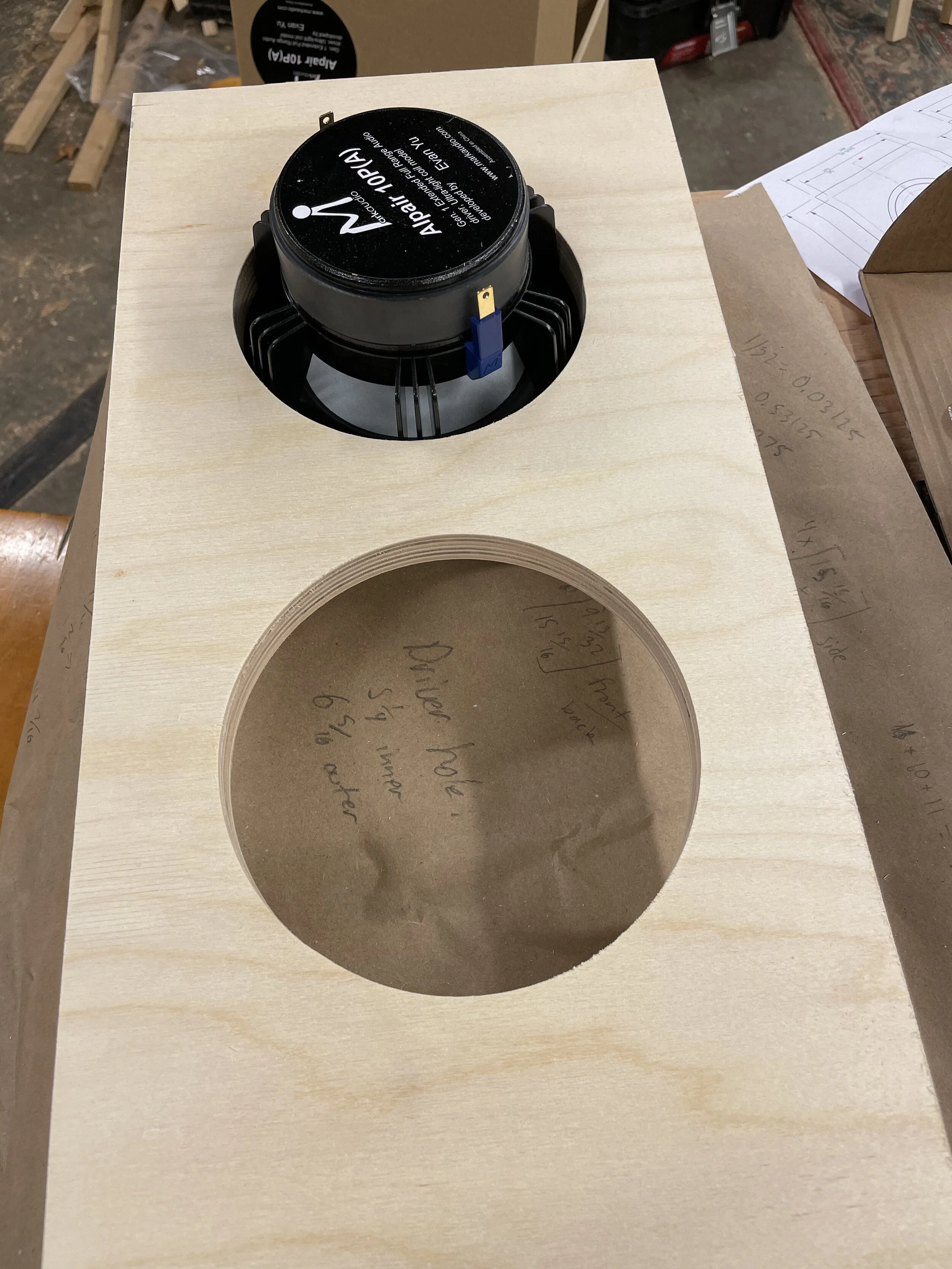

Here you can see the issue: the driver sits on top of the board, and not flush with it. This was fine and expected, I needed the first cut this way for now. Once I was sure I could make the initial cut correctly on the test piece, I cut out the holes in the actual front panels, as well as smaller ones for the vent holes. The jig didn’t do great with 2” diameter holes, but the vents I bought have a flange on them that covers the edge of the hole nicely, so I wasn’t concerned.


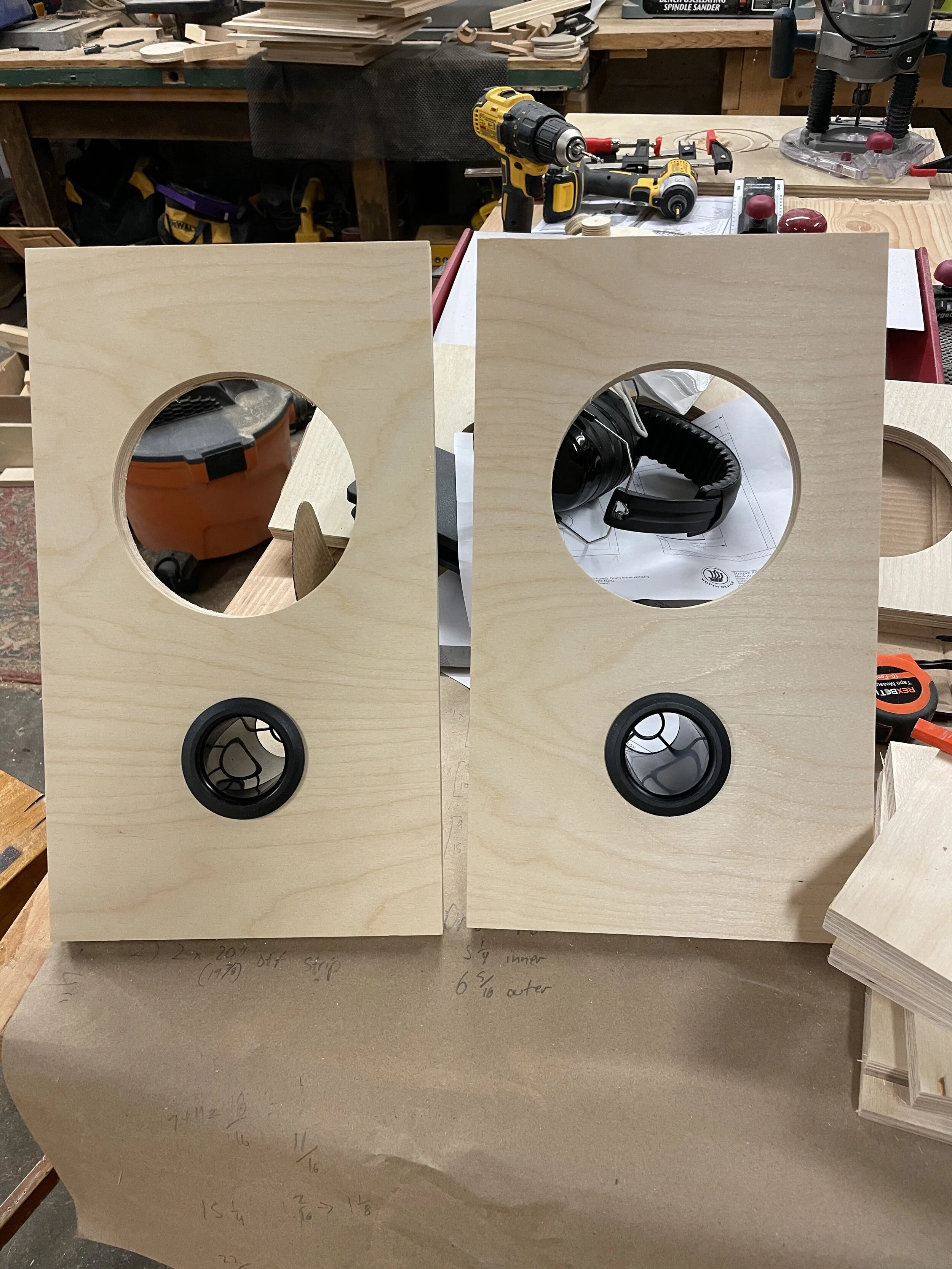
For the lip, I started by using a rabbeting bit on the router. Unfortunately, it didn’t make a big enough lip. So, the solution I came up with was to use the off cut circle from my test cuts to re-center the circle cutting jig, and use it to widen the hole to the exact size. The first picture here is routered rabbet, and then the next is the setup for re-centering the circle jig. Next, there’s a comparison between the widened lip (left) and the original one (right) where you can see the difference in diameter if you look close. Finally, there’s a test fit of the driver and port.


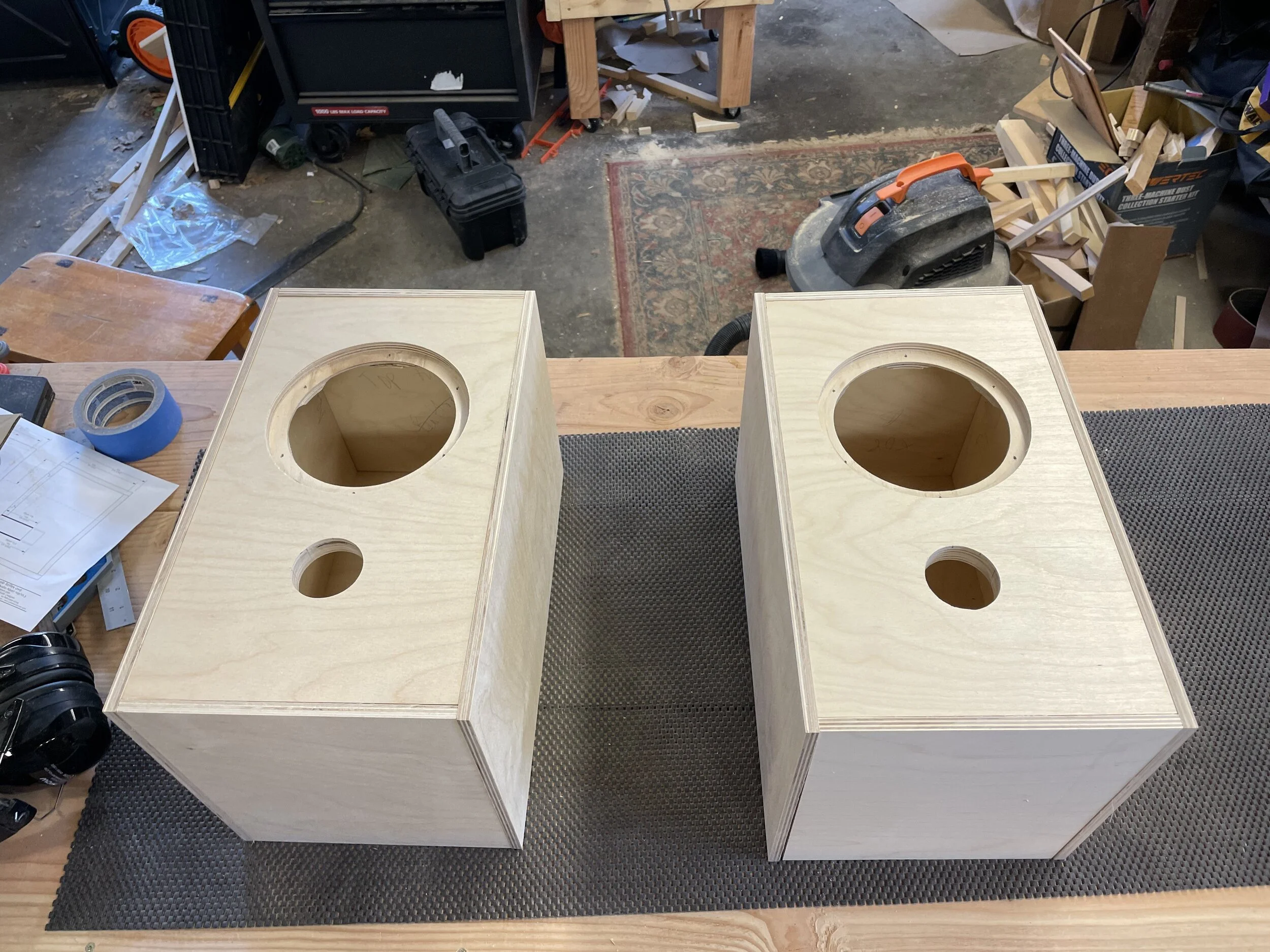
Next, I drilled some screw holes for mounting the driver. With the holes drilled, I could see where I could remove some extra material on the back with a router. This seemed like a bit of extra effort, but the plans said it was worth it, so why not. Here you can see that in the middle picture, and then another dry fit of something that resembles an actual speaker at this point.


I drilled some holes for the binding posts. Their diameter didn’t match up well with any drill bits I had (they were loose in the holes) but once I tightened them in place, they’re fine. I probably drilled them a little bit too low, but I didn’t want to be in line of fire of the port, in case that mattered at all. On the drill press, and a test fit:


All the internal faces needed some fabric damping. I ordered some quilt batting, but it turned out to be much thinner than I wanted, so I just folded it up twice, so it was 4-ply. I cut it with scissors and stapled it in place. I wound up needing to trim a bit more after a did another test fit, because the thickness of the batting would cause it to bunch up and overlap with the batting on an adjacent side. For the driver holes, I just drew an outline with marker.


Here’s a look inside the box (you can see just the rectangle cutout of batting for the binding posts), as well as the “exploded” view of all the panels:


Before I glued up the boxes, I did a dry glue to figure out how I wanted to position the clamps. Then I glued them up. You can see the squeeze out there, which was fine, I didn’t want to wipe it because that would make it harder to sand off (flush trim router bit action coming up soon). I could only clamp one speaker at a time, due to the number of clamps required. I considered using this as an excuse to nearly double my clamp collection in one go, but realistically, I have a lot of clamps as is and needing this many is a pretty rare circumstance.


In between the two glue ups, I tested out a couple different stain options. I wound up going with cherry, but candlelight was a close second. The test piece I had used for all the hole cutting did, like, triple duty during this project:
With the glue on both cabinets dry, it was time to trim off the excess. Here you can see both the squeeze out and the slight overhang of the rabbets:


A quick pass with a flush trim router bit cleaned things up pretty good! A “flush trim bit” is a bit with a bearing on it the exact diameter of the cutter. The bearing rides on the face of the plywood, and the bit cuts everything to exact level of the bearing. The last picture shows a trimmed box vs. an untrimmed one.


Getting close! Next up was to give everything a good sand to clean up any router roughness/burn marks/leftover glue. First picture is unsanded, then sanded.


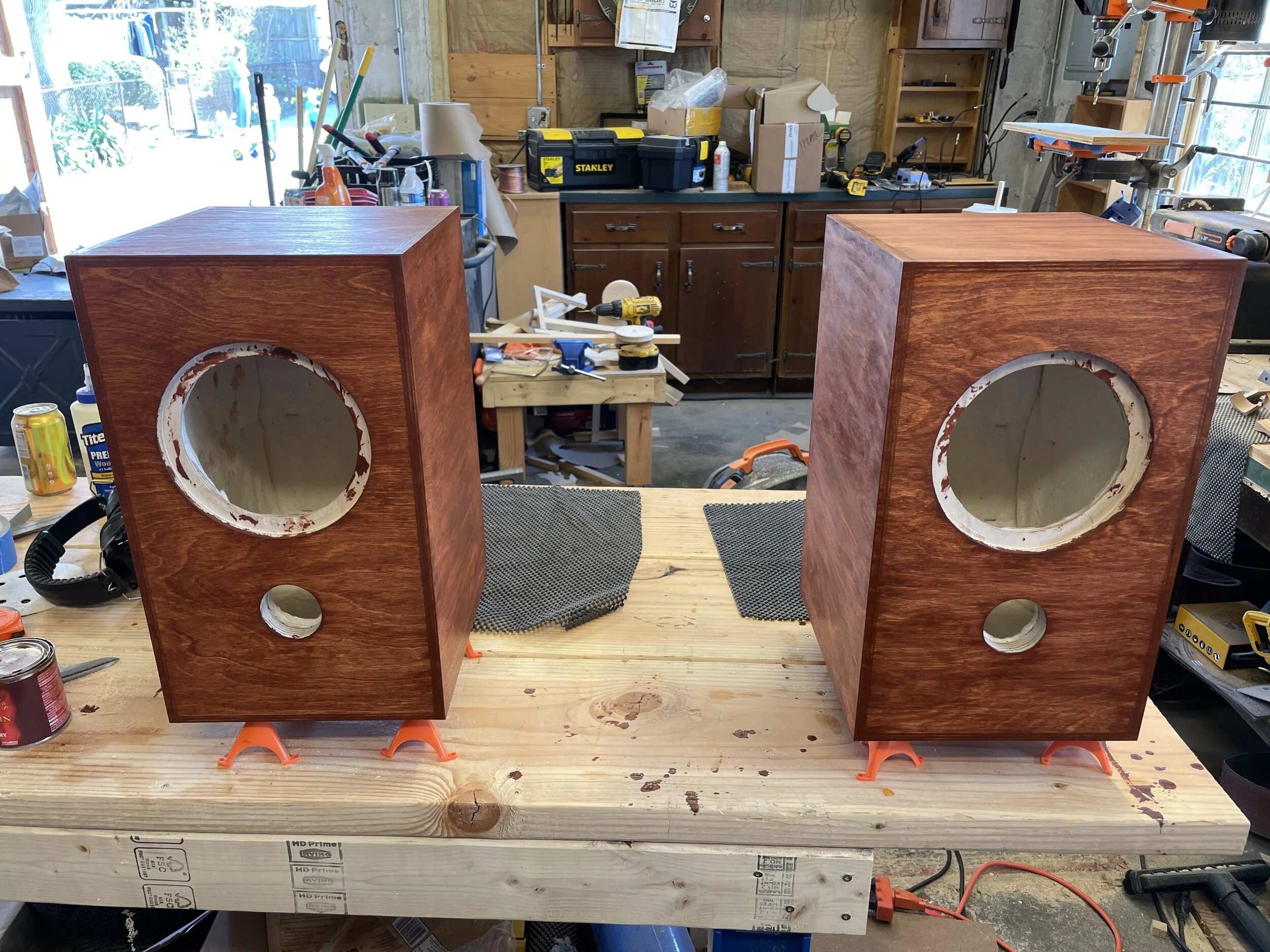
Puttin’ on the finish, coach. First goes pre-stain conditioner, then stain. This stain was fine although it really really wanted to be blotchy, even with the conditioner. One thing I wish I had done was get stain on the lip of the driver mount. You can see a bit of unfinished wood peeking out if you look at the right angle. I did two coats to give it some richness:


The finish here was shellac. Shellac is super easy to work with, dries quick, and as long as you’re not building something you’ll put beverages on (it’s soluable in alcohol, so if you spill your Old Fashioned on it, it’s gonna melt), will be plenty durable. First pic shows a shellac’d box on the left and an unfinished one on the right, the rest show them with all the shellac on them. I think I did 3 coats total.


Time to install the hardware and we’re done. First I glued the ports in place with silicone glue to give them a good airtight seal (I checked to make sure I had enough room to get at the binding posts with the ports in place before I glued them). Then I screwed in the binding posts.


Next I made the internal wires. One side fits on the binding post, the other side came with the speaker driver as a sort of quick connect. I soldered these in place so they’d have a secure connection and never come loose, and then attached them to the binding posts at an angle to try to keep them from bumping the port. The little helping hands clips are super great for holding things you’re soldering.


Finally, I attached the gasket to the driver, plugged them in, and screwed them in place, and they were done!


And here they are in their new home:


So, the million dollar question: how do they sound? In my humble opinion, really good! The speaker they replaced are the Klipsch RP-600M, which is a nice little speaker. Compared to those, the Model A have two major advantages: first, they image much better (i.e. you can “see” where the different instruments are coming from much more clearly). Second, they blend with my subwoofer much better - it’s not nearly as obvious when the subwoofer is taking over the bass duties. I will say they do need a little bit of EQ to sound their best, as they can sound just a tad thin on vocals sometimes, where the other instruments seem to overwhelm the singer. But once they’re dialed in, they’re a clear upgrade from the Klipsch! This driver would probably be better suited to a more complex design, and since I overbought plywood, I may take a crack at a more complicated box next. We’ll see!
Parts List/Links
I think the only other thing, besides tools, were some wire, which I had on hand, and staples in a staple gun, which I also had just lying around.